Chrysler TorqueFlite 727 Rebuild
You WILL need a manual to do this work. These are just my notes to supplement the manual. You will not be able to do this project without the book. I have included none of the gaps, end plays, or other specifications. If you do not have the IH service manual, you can buy a TF 727 tranny rebuild manual from most tranny shops. It is word for word identical to what you will find in the IH service manual. BUY THE BOOK.
Tranny Removal
- Drain tranny – hopefully you have a drain plug installed or you are going to make a mess.
- Coolant lines. The rear line is the return line. Rear Return Right. Easy to remember.
- Remove speedo cable.
- Disconnect kickdown lever from throttle assembly. There is a small c-clip that fits on the inboard end of the kickdown u-rod at the throttle assembly. Pull c-clip, slide kickdown lever off the side, replace the c-clip so you don’t lose it.
- Pull tunnel cover. Pull lever assembly. Remove shift cable end from lever assembly.
- Remove t-case shift lever knob.
- Remove ground wires from t-case bolts
- Remove neutral safety switch and 4 wheel engaged switch caps.
- Remove front and rear drivelines.
- Remove the tranny inspection cover from bottom of tranny.
- Unbolt 4 bolts holding torque converter to flex plate.
- Unbolt two bolts holding tranny to crossmember.
- Unbolt nuts and bolts holding passenger side of cross member to frame.
- If you are reusing your torque converter, mark its position relative to the flexplate so you can get the lugs for the torque converter lined up to the correct holes on the flex plate. The lugs and holes are not truly symmetrical and only go on one way.
- Unbolt and remove transfer case – careful it is heavy. A couple of the t-case bolts must be accessed through the tranny tunnel
- Loosen the nut holding the bull gear on. It is torqued to around 300 ftlbs.
- Slide tranny jack under tranny pan. Take weight of tranny onto jack.
- Support rear of engine with beam laid across fenders and chain, rope, etc under rear of engine.
- Loosen tranny to engine bolts. Double check for any stray connections.
- Unbolt shroud from radiator so blades don’t come into contact when engine tips to rear.
- Pull tranny bolts. Pull tranny back a couple inches so flex plate clears engine housing. Lower tranny. My tranny tends to hang up on my tailpipes. It is a very tight fit. Greasing the front sides of the tranny housing might be a good idea.
- Once the tranny jack is all the way down, it is unlikely you will have room to roll the tranny from under the truck, unless your truck is very, very tall. You will need to lower the tranny off the jack. Couple methods. One is to use a cherry picker to hold the tranny up with a chain through the tunnel cover. Another, is to slide the tranny off the jack and down a plywood ramp. Alternatively, you can jack your truck up and put it on jack stands to clear, but you are likely to have to go very, very high to do this. I do not like climbing around under my truck when it is that high, even if it is on jackstands.
- Double check that the rear of the engine is not sagging. You could easily break your engine mounts if it sags too much.
Tranny disassembly preparation
- If you have a tranny rebuild stand, this will make things easier. If not, your bench will work.
- Clean the outside of your tranny. If it is anything like mine, it will be very, very dirty. I used a pressure washer on mine to get all the loose stuff off. Book said wash it first so you don’t get gunk from the housing onto the parts. I think the book assumes a partial rebuild where you get to what is wrong and then start rebuilding without finishing the teardown, in which case knocking gunk from the housing onto parts would be a real concern. With a complete teardown, however, washing last makes more sense. I washed mine once it was empty, also.
-
- Put your tranny on a stand or on a bench. Make sure your bench is clear of everything. There are lots of little clips, washers and parts inside an auto tranny. Start with a clean bench, and end with a clean bench to make sure you don’t forget any parts. I laid a sheet of 8 mil white plastic over my bench to give me a sterile working environment.
Tranny disassembly
- Tranny gets disassembled front to rear.
- Pull Torque Converter off. It will be about half full of tranny fluid. Be careful not to dump it all over.
- Pull the shift lever connections.
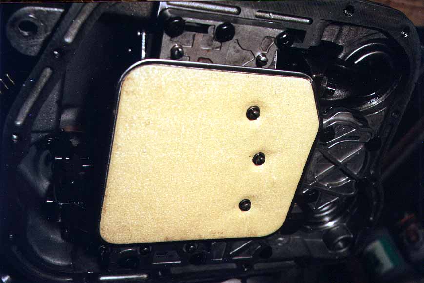
- Pull the tranny pan.
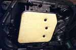 Remove the tranny filter. It is held
on with three machine screws.
Remove the tranny filter. It is held
on with three machine screws.
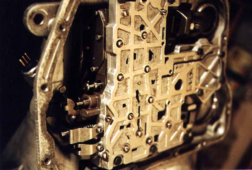
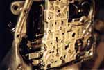 Pull the valve body. Be very careful with the valve
body. Keep it very
clean. It is held on with 6
or 8 bolts. Once the bolts
are pulled, slide it out carefully. It has an arm attached that runs
back into the tail housing for the parking gear engagement. That arm should pull right out.
Pull the valve body. Be very careful with the valve
body. Keep it very
clean. It is held on with 6
or 8 bolts. Once the bolts
are pulled, slide it out carefully. It has an arm attached that runs
back into the tail housing for the parking gear engagement. That arm should pull right out.
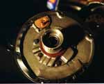
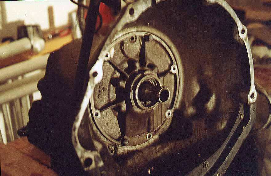
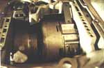
 Go back to the front of the
tranny. You will now be
looking at the tranny oil pump housing. It is a large disc set into the
housing with several bolts.
The input shaft extends out the middle of it. Around that shaft is the
spindle that the torque converter rides on.
Go back to the front of the
tranny. You will now be
looking at the tranny oil pump housing. It is a large disc set into the
housing with several bolts.
The input shaft extends out the middle of it. Around that shaft is the
spindle that the torque converter rides on.
- Measure the input shaft end play. Check if it is with specs. If it is not, the thrust washer you will find behind the oil pump housing will need to be replaced with one to correct the end play.
- The disassembly process is easiest if the tranny is in a vertical position with the tail down. I happened to have a wooden box that was just the right dimensions to do this. Alternatively, you could buy some ¾” plywood or OSB and cut an appropriate shaped hole, then hang it between two sawhorses.
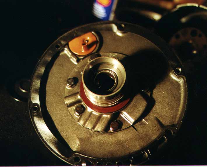
- Tranny pump removal
- Remove the 6 or 8 bolts holding the pump to the housing.
- You will need to fashion a pump puller. I bought two lengths of all thread (threaded rod) of the correct pitch and size. Two of the pump bolt holes are threaded. Mine were at 3 and 9 o’clock. I measured the distance across the face of the pump from those two threaded holes. I then drilled a pair of appropriately spaced holes slightly larger than the all thread in some 2x2 square tubing that was long enough to span the pump housing. I threaded the all thread into the holes in the housing, then slid the 2x2 over that. I placed nuts and washers on the all thread, then used a box wrench to turn the nuts. I turned the bolts evenly, a couple turns one side, a couple turns the other, until the pump came loose. I was then able to hold onto the 2x2 and finish pulling the housing out. Be careful not to nick or scar the spindle the torque converter rides on.
 With the housing out, unbolt the
pump from the housing.
Inside the pump are a pair of metal rings, one off sized from
the other. Pull and
inspect those.
With the housing out, unbolt the
pump from the housing.
Inside the pump are a pair of metal rings, one off sized from
the other. Pull and
inspect those.
- Pull the front seal
- Pull and replace the bushing in the front of the housing behind the main seal. That is what prevents fluid from draining out of your torque converter over night.
- Pull the front seal.
- Install a new front seal.
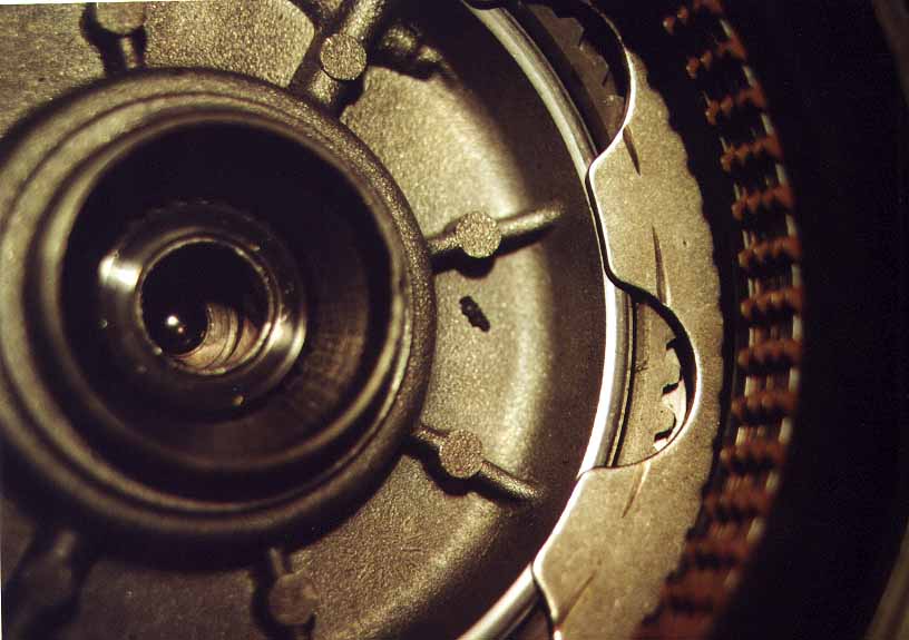
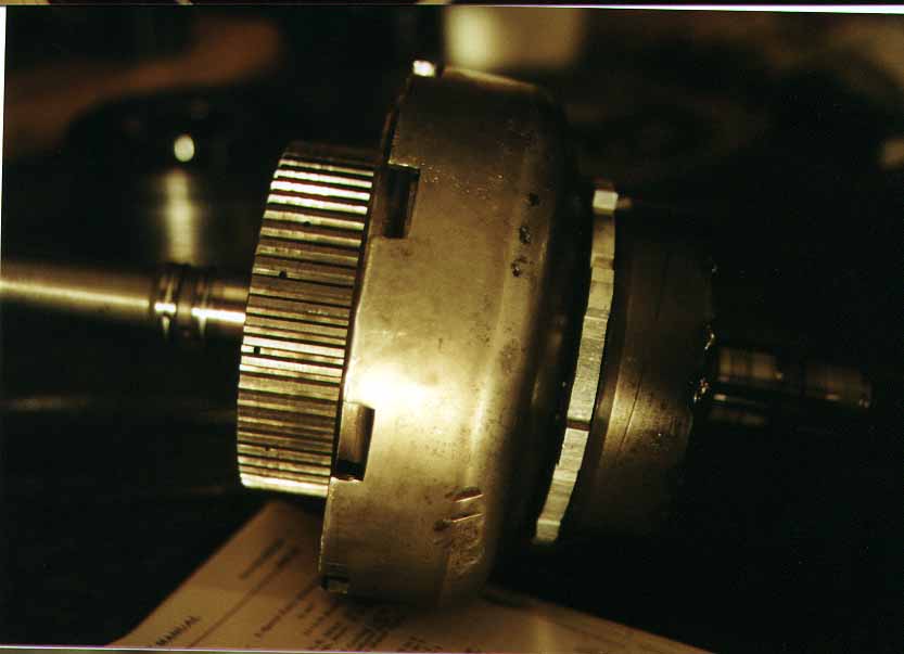
Input shaft disassembly
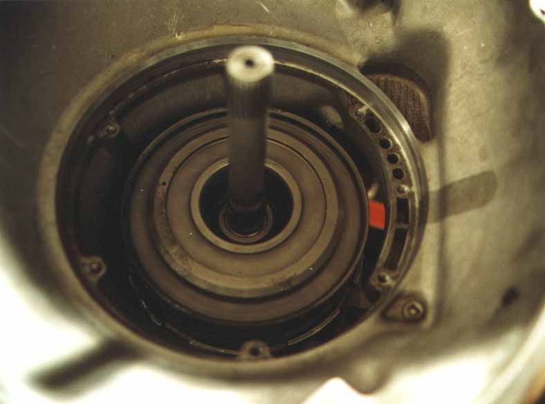
 You will now be looking at the end of
the input shaft assembly.
You will see a large drum, with the input shaft sticking out the
end. You should see on the
face of the drum a thrust washer about 4 inches across and about a
quarter of an inch thick.
That should pull right off the face. Keep it. You will need it later. You can then slip the
2nd/3rd gear drum off the clutch retainer drum.
You will now be looking at the end of
the input shaft assembly.
You will see a large drum, with the input shaft sticking out the
end. You should see on the
face of the drum a thrust washer about 4 inches across and about a
quarter of an inch thick.
That should pull right off the face. Keep it. You will need it later. You can then slip the
2nd/3rd gear drum off the clutch retainer drum.
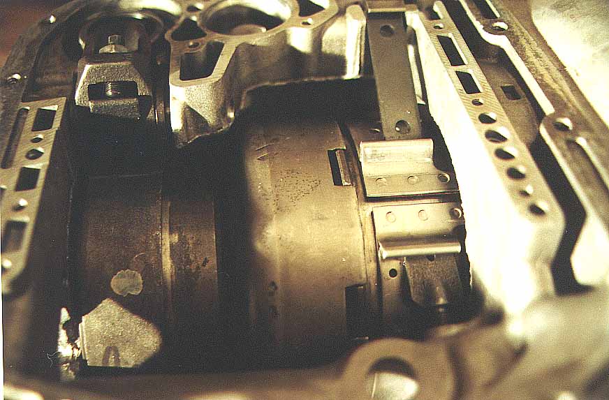
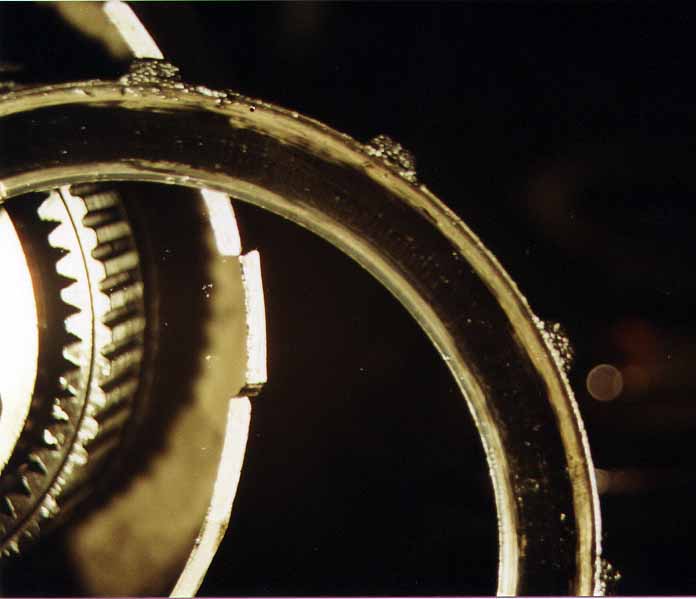
 Around the outside of the drum is the
2n3/3rd gear band.
To release the band, loosen the adjusting stud lock nut. Loosen the adjusting stud until
you can slip the bar that goes from the adjusting stud clip to the
band. Once you pull that
bar, the adjusting stud clip will try to fall into the tranny. Hang onto it.
Around the outside of the drum is the
2n3/3rd gear band.
To release the band, loosen the adjusting stud lock nut. Loosen the adjusting stud until
you can slip the bar that goes from the adjusting stud clip to the
band. Once you pull that
bar, the adjusting stud clip will try to fall into the tranny. Hang onto it.
- With the bar and adjuster removed, you can now pull the band out the front of the tranny.
- With the band removed, you can now pull the front drum straight out the front. Be careful not to damage any of the bearing surfaces on the input shaft.
- Now, grasp the input shaft and pull it out the front of the transmission. It should pull straight out. Mine did not. That complicated things for me. I had to pull my entire input/output shaft assembly as a unit, then beat on the driving shell till the clutches broke free and the two assemblies separated. This resulted in a warped driving gear which had to be replaced, but Rick W had some spare 727 parts he gave me to use.
Input shaft disassembly 2nd/3rd gear clutch pack
 The clutches for the pack are held on
by a wavy snap washer near the lip of the clutch retainer (drum). Several people I spoke with had
had the wavy snap ring replaced with a flat snap ring. A shop I spoke with told me this
allows the piston to engage the clutches faster, resulting in less
wear. I am not sold on
this. I am afraid it would
force the piston to travel farther to get full clutch engagement. Although my clutches were in
good shape, and had a flat snap ring I replaced it with a wavy snap
ring, per manual specs.
Some 727's use the flat ring if it's either heavy duty or in a
one ton truck or motor home.
The clutches for the pack are held on
by a wavy snap washer near the lip of the clutch retainer (drum). Several people I spoke with had
had the wavy snap ring replaced with a flat snap ring. A shop I spoke with told me this
allows the piston to engage the clutches faster, resulting in less
wear. I am not sold on
this. I am afraid it would
force the piston to travel farther to get full clutch engagement. Although my clutches were in
good shape, and had a flat snap ring I replaced it with a wavy snap
ring, per manual specs.
Some 727's use the flat ring if it's either heavy duty or in a
one ton truck or motor home.
-
- Once the snap ring is off, the clutches and clutch plates should pull off the inner gear. Discard the clutches and inspect the metal clutch plates. It cost me $15 to replace mine. I did not bother inspecting. It was worth $15 to me to replace them.
- Below the clutch plates and discs is the piston. It is held on by a snap ring, but has 9 or so heavy springs putting pressure on it. I took mine to a shop to have them pull it apart. They had a cute little foot press that did the job in about 30 seconds. It is important to pull the piston assembly apart. There is a rubber seal around the piston that needs to be replaced. If that seal gets hard or brittle, you will lose pressure behind the piston, and you will not get enough pressure against the plates to keep them from slipping. Your rebuild kit will come with the correct seal.
With the input shaft assembly free, you can now see the output shaft assembly. This is all held together by a snap ring on the end of the output shaft. Look carefully at the end of the output shaft. There should be a thrust washer on the end. Don’t lose it.
Output shaft disassembly
 Remove the small snap ring. With it off, just start pulling
the output assembly pcs off.
There will be a planetary gear set, then some gear rings, keep an
eye out for thrust washers and thrust plates. There will be a few of
each. Note the location and
condition of each.
Remove the small snap ring. With it off, just start pulling
the output assembly pcs off.
There will be a planetary gear set, then some gear rings, keep an
eye out for thrust washers and thrust plates. There will be a few of
each. Note the location and
condition of each.
Output shaft disassembly – low reverse clutch pack
 The low/reverse clutch pack is held in
with a snap ring. Pull the
snap ring and the clutches should pull right out. The reverse piston spring is a
large metal washer similar to the clutch spring for a standard
transmission. Pull the snap
ring holding it in place.
Below the snap ring is a fiber spacer. Pull and keep that spacer. The piston will then slide
out. Pull it and replace
the seal on it.
The low/reverse clutch pack is held in
with a snap ring. Pull the
snap ring and the clutches should pull right out. The reverse piston spring is a
large metal washer similar to the clutch spring for a standard
transmission. Pull the snap
ring holding it in place.
Below the snap ring is a fiber spacer. Pull and keep that spacer. The piston will then slide
out. Pull it and replace
the seal on it.

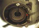
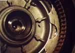
This is what my clutches looked like. No friction material left at all. Not sure how it even went down the road.
Output shaft disassembly - continued
- After the planetary gear, gear ring, clutch pack, clutch retainer, thrust plates and washers are out, you will be looking at the driving shell. It is a large cup shaped pc of metal that most of the front output shaft assembly pcs were riding in.
- Pull the driving shell. In the middle of the driving shell is the sun gear. Slide the driving shell off the output shaft. Then, remove the snap ring on the front side and slide the sun gear out.
- Check the driving shell for roundness. Check all the ring gears and planetary gears for damage and wear.
- Behind the driving shell is the reverse planetary gear assembly and reverse drum. Both those slide off the output shaft.
- Next, loosen the reverse gear drum band from below until you are able to pull the band strut (flat bar). With the strut loose, you can pull the adjustment stud out, and pull the reverse gear band.
- Pull the reverse gear drum.
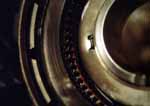
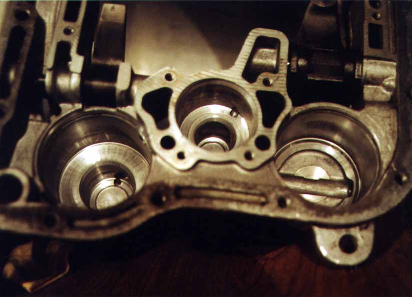
- Looking down into the tranny, you will now see several small
cylinder bearings, about the size of pencil erasers, standing on end
around a center geared ring.
The ring will slide out.
That will release the bearings and the small metal accordian
springs. Remove all the
springs and bearings. I
replaced mine. They were
$30 or so, I think. This
part is called a sprag. I would recommend replacing it on every rebuild
and replace it with a bolt in heavy-duty unit, not a stock one. The
stock one loves to fail and or blow apart under hard use, especially
when you spin a wheel and then hit a dry stop.
-
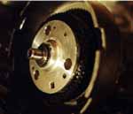
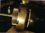
Rear Disassembly
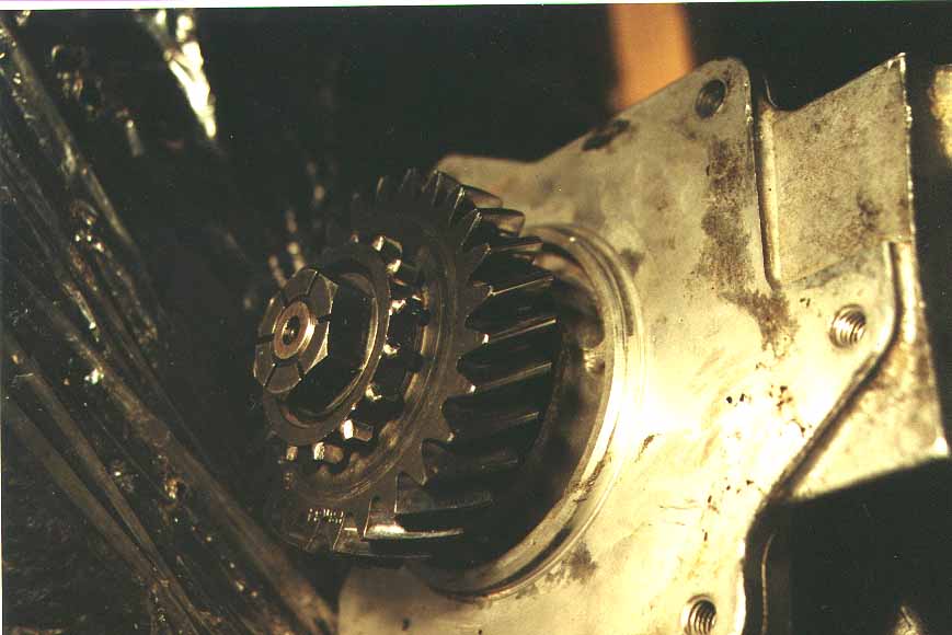
 Unthread the nut at the rear of the
tailhousing, and slide the bull gear off.
Unthread the nut at the rear of the
tailhousing, and slide the bull gear off.
- Unbolt the tailhousing and slide it off.
- You will now be looking at the governor assembly and output shaft support.
- The governor assembly is held in by a snap ring. Pull the snap ring and it will will slide out of the output shaft. Put the small snap ring back on the end of the governor
- Unbolt the aluminum output shaft support pc and pull it from the housing.
- Inspect the cam and surfaces the springs and bearings were riding on.
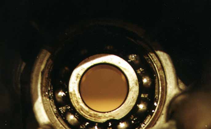
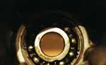 Pull the rear seals out of the end of
the tailhousing. There are
two seals in this spot, one facing to the front of the housing and one
to the rear. Replace both when you get to reassembly. remove the snap ring in front of
the rear bearing, then knock the tailhousing bearing forward, out of the
housing. Inspect the
bearing for wear. That
bearing is very difficult to find new (Impossible?) I talked to several bearing and
parts houses and none could find a new one. It is part number MRC
307M5. If you find a
source, please let the IH community know. I ended up using an inspected
used part.
Pull the rear seals out of the end of
the tailhousing. There are
two seals in this spot, one facing to the front of the housing and one
to the rear. Replace both when you get to reassembly. remove the snap ring in front of
the rear bearing, then knock the tailhousing bearing forward, out of the
housing. Inspect the
bearing for wear. That
bearing is very difficult to find new (Impossible?) I talked to several bearing and
parts houses and none could find a new one. It is part number MRC
307M5. If you find a
source, please let the IH community know. I ended up using an inspected
used part.
Update:
Dave Steffens recently sent me the following E-Mail:
Applied Industrial Solutions, Long
Beach, Ca 562-437-2201 Has the MRC 307MS
bearing
$43.90
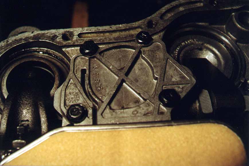
Servo disassembly
- I put the tranny back on the bench to work on the servos.
 The servos are held in by snap
rings. Put a large C-clamp
over a large socket (1 1/8”) and onto the servos to compress them, then remove the
snap rings. Slowly release
the C-clamps. The servos
will pull straight out. Be
very careful not to score the walls of the servos. That is housing material and
deep gouge could mean the end of your housing.
The servos are held in by snap
rings. Put a large C-clamp
over a large socket (1 1/8”) and onto the servos to compress them, then remove the
snap rings. Slowly release
the C-clamps. The servos
will pull straight out. Be
very careful not to score the walls of the servos. That is housing material and
deep gouge could mean the end of your housing.
- Take the servo pistons apart. The reverse piston has a rubber seal. Replace it. When you replace it, make sure the cup is down (to the inside). The 2nd/3rd gear piston is kind of a piston within a piston.
- Replace all the metal circle seals. You can hone the server bores with a brake shoe hone, but be careful not to take too much off.
Final disassembly
- Dunk the housing or take it down and pressure wash it. In any case, make sure it is completely clean. You don’t want any gunk getting in during rebuild. I took mine over to Kevin’s house and he used his parts washer on it to get it shiny and clean. Then it was time for inspection and reassembly. I am not going to go into the inspection process. Check every bushing, every snap ring, every clearance, per manual specifications. I cannot remember them all, and do not want to try
- Punch out the shift lever seal.
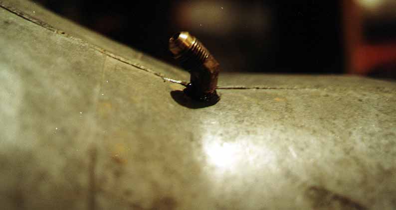
Breather tube
 While you have your tranny apart, it
is a good time to install a breather tube. When you think about it, the top
of the tranny is not very high, and it is not difficult to get water
into the transmission. To
fix this, plug the breather hole in the pump housing and drill a new
one.
While you have your tranny apart, it
is a good time to install a breather tube. When you think about it, the top
of the tranny is not very high, and it is not difficult to get water
into the transmission. To
fix this, plug the breather hole in the pump housing and drill a new
one.
- I drilled and tapped a hole in the tranny, right where the housing flares to accept the torque converter. I then installed a brass elbow with lots of permatex. Make sure it does not intrude into the body of the tranny and interfere with any of the parts in there.
- I tapped the oil pump housing breather hole, and installed a short bolt with lots of permatex to seal that hole. Now, no more water getting into the tranny.
Reassembly
- Installation of that bearing was problematic. It was just too big, although it mic’d out to be the same as my old one. I ended up putting my tailhousing in a large pot of boiling water for about 10 minutes. Then, I pulled the housing, quickly dried it, and tapped the bearing into place. It went in and did not seem to bind once it was in, so it appears to have been the correct procedure. Install rear bearing snap ring retainer. Another method is to place the housing in the oven and heat it up, and put the bearing in the freezer to chill it. Between the two, you should get enough shrinkage and growth to get it to fit.
- Install the rear seals. Two of them. You need to buy those seals separate because they do not come in your standard rebuild kit. I put a little RS on the outside of the seals. The inner seal installs pointed inward, the outer pointing outward. I found this out later, but got lucky and installed them this way to begin with.
- Thread two lengths of all thread into the tranny housing to use as guides to install the aluminum output shaft support. Then, slide the output shaft support into the housing.
- Install the governor.
- Bolt the tailhousing to the main housing.
- Flip the tranny on its tail again
- Install the bearing race in the rear of the main housing. Then, install the bearings and springs. I found it was easiest to place the bearings in, then squeeze the springs in behind. Spin the race to make sure all the bearings are seated correctly.
- Inspect the back side of the reverse drum. Make sure the lip that holds the bearings back against the cam is in not worn off. It should be about an eighth of an inch deep and about that wide. Slide the drum over the bearings.
 Install new rings and seals on the
servo pistons and slide into the bores. Remember to place the lip of the
seal for the reverse band servo in or you will cut it when you install
it. Use your c-clamp and
sockets to compress the servos and install the snap rings.
Install new rings and seals on the
servo pistons and slide into the bores. Remember to place the lip of the
seal for the reverse band servo in or you will cut it when you install
it. Use your c-clamp and
sockets to compress the servos and install the snap rings.
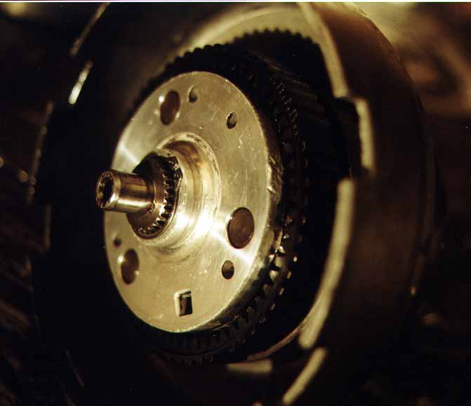
Output shaft assembly
- Slide the output shaft through the reverse drum, through the tailhousing. Slide on the bull gear. Thread on the nut and tighten securely.
- Install the ring gear, and the rear planetary assembly. Make sure the lugs on the planet gears engage the lugs on the reverse drum. Then, install the reverse band.
- Install the ring gear, followed by the planetary gears. Make sure you get the thrust plates and washers in the correct locations.
- Install the sun gear into the driving shell, and slide assembly onto ouput shaft. There is a thin thrust plate on the back side of the driving shell. Make sure it is there.
- Install the ring gear inside the driving shell. Then slide the planetary gears on. Again, make sure the thrust plates and washers are in the correct locations.
- Install the snap ring on the end of the output shaft.
- Place the thrust washer on the end of the output shaft.
Input shaft assembly
- I installed a new piston seal, then took it to the tranny shop to have the piston pressed back on.
- With the part back, I installed the clutches and plates into the clutch retainer, and followed up with a flat snap washer.
- Slide this assembly into the driving shell, turning slightly left and right to engage the clutch teeth on the driving shell ring gear. Eventually, it will all slide together. It took me about 30 seconds of wiggling to get it all engaged properly.
- Next, install the clutches into the 2nd/3rd gear clutch retainer. On this one, you have the option of using a wavy snap ring or flat snap ring and spacer. The wavy washer on the 2nd/3rd gear clutch is what the book specs. It gives you a slightly softer shift, but generates more heat because it does allow the clutches to slip a little. Some folks swap a flat snap ring for this. The two shops I talked to said this gives you a faster clutch engagement for less wear on the clutches. If you do this, you will need a spacer snap ring to take up the slack. I liked the nice tight shift I had with the flat washer, but swapped to a wavy washer, per book specs.
- Slide the input shaft/clutch pack over the reverse clutch pack retainer. Make sure the lugs in the 2nd/3rd gear retainer set into the slots in the driving shell.
- Install the 2nd/3rd gear band. Make sure the tabs are on the inside of the band or they won’t clear the housing. Install the band strut, and the adjusting stud/lock nut. The tranny shop recommended a ½” clearance between servo and clutch levers. That is slightly less than the manual specs out.
At this point, the body of the tranny is pretty much together. Double check for any parts laying around on the bench or on the floor. If you don’t find any, then it is time to button things up.
Pump housing installation
- Install the tranny pump into the tranny pump housing.
- Thread a length of all thread through one of the tranny bolt holes and into the tranny housing to use as a guide.
- Slide the pump housing along the all thread, until it mates to the housing. Apply a small amount of tranny assembly lube to the edge of the housing around the rubber seal.
- Install the housing bolts, and evenly tighten until the housing bottoms out. Tighten bolts per specifications.
- IMPORTANT: my manual says those bolts should be torqued to 170 ftlbs, but I believe it should be 170 inlbs.
 Install the shift lever seal. The manual calls for using a deep
socket to do this. I did mine
wrong and had to do it again.
However, the second try, I pulled the valve body, and the seal went
right on. I then reinstalled
the valve body.
Install the shift lever seal. The manual calls for using a deep
socket to do this. I did mine
wrong and had to do it again.
However, the second try, I pulled the valve body, and the seal went
right on. I then reinstalled
the valve body.
Valve body installation.
- On the top of the valve body shift lever there is a small snap ring. Remove that snap ring and remove the washer to reveal an o-ring. Pull and replace that o-ring, then replace the washer and snap ring. Be careful when doing this because the ball bearing shift selector can pop out, and you will spend the next 15 minutes getting it back in place correctly.
- Turn the tranny onto its left side and slide the parking gear arm through the mainhousing into the tailhousing where it will push through the slot between the parking gear ratchet and the housing.
- Gently slide the shift lever column through the housing and set the valve body in place.
- Install the bolts and tighten per specifications.
- Install the tranny filter
- Install the tranny pan gasket and tranny pan.
- Install the tranny pan bolts. Tighten per specifications.
Miscellaneous
- Install the shift lever brackets
 Put some tranny fluid on the front tranny seal,
then install the torque converter. Make sure the converter is fully
seated. The lugs for the
flexplate end up RECESSED into the housing about half an inch past
flush. The converter seems
to have three depths it sits on.
Put it on, it sits on one depth, wiggle it and push it, it goes
to another, more wiggling and pushing, and it WILL sink to the correct
depth. They ALL end up with
the lugs about half an inch recessed into the main portion of the tranny
housing face. If you don't
get it deep enough, you will be pulling it to replace your tranny pump,
or worse.
Put some tranny fluid on the front tranny seal,
then install the torque converter. Make sure the converter is fully
seated. The lugs for the
flexplate end up RECESSED into the housing about half an inch past
flush. The converter seems
to have three depths it sits on.
Put it on, it sits on one depth, wiggle it and push it, it goes
to another, more wiggling and pushing, and it WILL sink to the correct
depth. They ALL end up with
the lugs about half an inch recessed into the main portion of the tranny
housing face. If you don't
get it deep enough, you will be pulling it to replace your tranny pump,
or worse.
Install the tranny into the rig.
- Take new converter over to rig. Trial fit the torque converter to the flex plate. Put it up against the flex plate and see which orientation of the bolt holes to torque converter lugs match up. Then, mark the flex plate and torque converter (I just shoot some bright spray paint on one spoke of the flex plate. The overspray marks the lug of the torque converter that mates up to it. Then take the torque converter off and reinstall on the tranny. The reason you did this is that the TC only goes on the flex plate in one orientation. If it is off by 45 degrees, one or two bolts will line up, but not all four. It could take several tries before you find the right combo. It is much easier to try the different possibilities with the torque converter off, so you can easily get to all four flex plate bolts at once, then do it once the tranny is mated up so you can only get to two or three lugs at a time.
- Drag tranny over under the rig.
- Manhandle it up onto the jack (helps to have a friend for this).
- Jack the tranny up into place.
- Bolt tranny to engine. Don’t forget the ground wire or the filler tube. Don’t pinch anything between tranny and engine. You might need to tip the engine to the rear to get things lined up correctly.
- Climb underneath. Bolt torque converter to flexplate.
- Install cross member
- Bolt tranny to cross member
- Install coolant lines.
- Install shift cable onto shift lever brackets.
- Tighten tranny to engine bolts.
- Install t-case
- Install speedo cable
- Install drivelines
- Fill tranny with fluid. Start with 4 quarts, then start engine without revving it, and add 5 more quarts. Recheck and add more until full.
- You will need to reset your TV, also known as kickdown linkage. Remember, lengthen equals later. That is, as you lengthen the linkage, by rotating the head on it, the linkage gets longer, which increases pressure inside the tranny. This causes increased pressure inside your tranny, resulting in later, faster, more positive shifts. The faster shifts mean less clutch wear. Better for tranny. But, if you overdo it, your tranny will be shifting too late, and too hard. Hard on engine and hard on tranny. 1st to 2nd shift should be somewhere around 8-10mph and 2nd to 3rd will be around 35-40 under easy acceleration. Under hard acceleration, shifts 1st to 2nd should be between 35-40, and 2nd to 3rd will be at 50-60. Adjust it to match your driving style, but later, harder shifts are better for your tranny, to a degree.
- Also you should use Vaseline on all the lip seals and seal lips, helps keep the lip seals from getting cut when you install them and helps keep the lips of the seals from getting galled on start up.
- It's also a good idea to put a little grease on the engine pilot hole so the converter can slide in and out of the hole freely. It will move in and out of the pilot as you increase or decrease the load.
I have not heard of any break in procedures for an auto tranny.
Remember, read your manual and follow its directions. This writeup is only to give you an idea of what I saw and did as I worked my rebuild. It is not intended to replace or supercede the manual. If you are not sure, ask. There are many good forums to get answers to questions. I relied heavily on Tom M, Snohomish Transmission, , Scott, my friends on the IHC digest, and on the Binder Bulletin. Good luck.