INDEX
Axle Shafts and Bearings
Assembly and Installation
Removal and Disassembly
Differential Bearing Preload and Drive
Gear Backlash
Differential Reconditioning
Assembly and Installation
Cleaning and Inspection
Removal and Disassembly
Differential Side Gear Clearance
Checking and Adjustment
Gear Tooth Contact Pattern
General Information
Lubrication
Rear Axle Assembly
Installation
Removal
Removal and Replacement of Drive Pinion
Flange and Oil Seal in Vehicle
Service Diagnosis
Service Procedures
Specifications
Tightening Reference
Special Tools
GENERAL INFORMATION (back to CONTENTS)
The 7-1/4 inch and 8-1/4 inch rear axles (Figs. 1 and 2) are semi-floating hypoid gear type in which the centerline of the drive pinion is mounted below the centerline of the ring gear. The drive pinion and the differential case with drive gear are mounted directly into the center section of the rear axle housing assembly. Access to the differential, drive gears and bearings is accomplished through the removal of a stamped steel cover which is bolted onto the rear of the axle housing. All components can be inspected, removed and serviced without removing the complete axle assembly from the vehicle. Ring gear diameter can be identified by observing the housing tube diameter. The 7-1/4 inch axle has housing tubes which are 2.5 inch (63.5 mm) diameter at the inner ends and 3.00 inch (76.2 mm) at the outer ends; the 8-1/4 inch axle has housing tubes that are 3.0 inch (76.2 mm) in diameter.
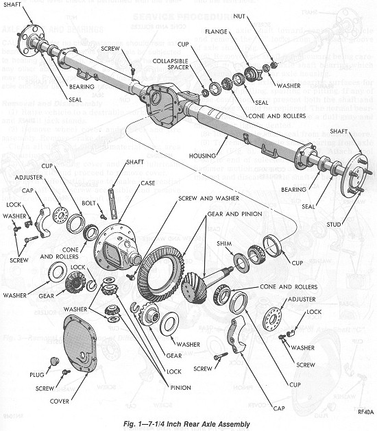
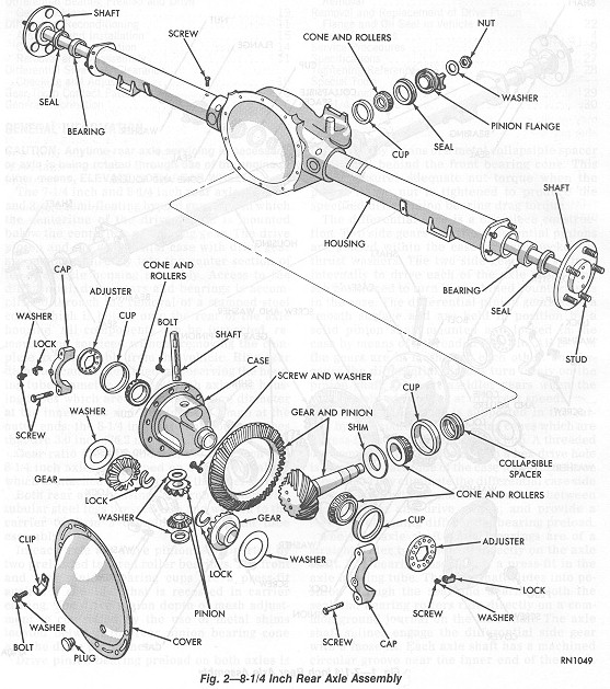
Gear ratio identification on the 7-1/4 inch and 8-1/4 inch axles is stamped on a small metal tag which is attached beneath one of the cover screws.
Both rear axle housings are iron castings with tubular steel legs pressed into and welded to the carrier to form a complete carrier and tube assembly.
In each axle the drive pinion is supported by two preloaded tapered roller bearings. The front and rear pinion bearing cups are a press-fit against a shoulder that is recessed in carrier casting. The drive pinion depth of mesh adjustment is controlled by the use of metal shims located between the rear pinion bearing cone and the drive pinion head.
Drive pinion bearing preload on both axles is controlled by means of a metal collapsible spacer positioned behind the front bearing cone. This spacer assures adequate nut torque when the pinion flange nut is tightened to produce the specified drive pinion bearing drag torque.
The differential case is a one-piĶce construction. Two side gears and two differential pinions are housed within the case and are backed by thrust washers. The two side gears are splined internally to drive each of the axle shafts, and are positioned to turn in machined counterbores in the case. The differential pinion gears have a smooth surface and are held in position by a solid pinion shaft mounted and locked in the case by means of a threaded lock pin. All four of the gears are in mesh with each other, and because the differential pinions turn freely on the pinion shaft, they act as idler gears when the rear wheels are turning at different speeds.
The differential case is supported in the carrier by two tapered roller bearing cones which are a press-fit on the differential case hub. A threaded differential bearing adjuster with a hex drive hole is located on each side of the case to perform three functions. They eliminate the differential case side play; they adjust and maintain backlash between the ring gear and drive pinion; and provide a means of obtaining differential bearing preload.
The rear axle shaft wheel bearings are of a straight roller type and roll directly on the axle shaft. The bearing assembly is a press-fit in the axle housing tube. The axle shaft slides into position through the seal and bearing. Both the seal and bearing rollers ride directly on a common ground journal on the axle shaft. The axle shaft splines engage the differential side gear with a loose fit. Each axle shaft has a machined circular groove near the inner end of the shaft.
The axle shafts are retained in the assembly by means of the ōCö locks positioned in the circular groove. When the axle shafts and ōCö locks are properly installed, the outer portion of the ōCö lock will be positioned in the machined recess of the side gear which will prevent the removal of the washer and the axle shaft. With the differential pinion shaft installed, and retained by its lock screw, axle shaft ōCö locks are securely locked in place and cannot slide out. Therefore, with the axial movement of the axle shafts controlled in this way, no axle shaft bearing end play adjustment is required.
Axle shaft bearings are lubricated by means of rear axle lubricant level being maintained in the tubes of the housing during operation.
A Sure-Grip Differential is available as optional equipment on 8-1/4 inch axle. It is a two piece construction and will be serviced as a complete assembly only. Refer to the Sure-Grip Differential Section of this Group for the servicing procedure.
Each axle is equipped with an external vent. On the 7-1/4 inch axle it is located on the left leg. On the 8-1/4 inch axle it is located on the right leg.
Fluid Level Check
For normal passenger car service, periodic fluid level checks are not required. At each engine oil change however, a fluid level check is recommended.
When this check is performed with the car in a level position, supported by the suspension, the fluid level should be between the bottom of the filler plug opening and a point 1/4 inch (6.4 mm) below the filler plug opening.
If the fluid level check is performed with the vehicle on a frame contact type hoist, with the axle hanging free, the fluid level should not be lower than the bottom of the filler plug opening.
CAUTION: Should the rear axle become submerged in water, the lubricant must be changed immediately to avoid the possibility of early axle failure resulting from contamination of the lubricant by water drawn into the vent hole.
SERVICE PROCEDURES (back to CONTENTS)
AXLE SHAFT AND BEARINGS (back to CONTENTS)
CAUTION: Under no circumstances should rear axle bearing cones, cups, bores or journals be subjected to heating with a torch, beating with a hammer or any other abnormal abuse, as permanent damage may result. Proper removers and installers are available and their use is highly recommended.
Removal and Disassembly
(back to CONTENTS)
(1) Raise vehicle to a desirable working height and install jack stands.
(2) Remove wheel cover and wheel and tire assembly. Remove brake drum.
Clean all dirt and foreign material from area of housing cover.
(3) Loosen housing cover and drain lubricant from rear axle and proceed to remove cover.
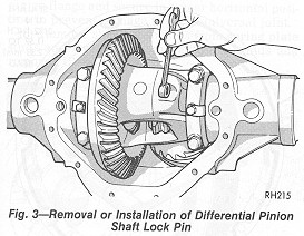
(4) Turn differential case to make differential pinion shaft lock screw accessible and remove lock screw and pinion shaft (Fig.
3).
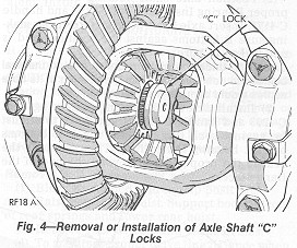
(5) Push axle shaft toward center of vehicle and remove the ōCö locks from recessed groove of axle shaft (Fig.
4).
(6) Remove axle shaft from housing being careful not to damage the axle shaft bearing which will remain in the rear axle housing.
(7) Inspect the axle shaft bearing surfaces for signs of brinnelling, spalling or pitting. If any of these conditions are present both the shaft and the bearing should be replaced. The normal bearing contact on the shaft will be a dull gray and may appear lightly dented.
(8) Remove axle shaft seal from housing bore.
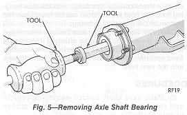
(9) To remove the axle shaft bearing from axle housing (Fig. 5), use Tool C-4167. Attach Tool C-637 to end of selected remover, using a slide hammer motion, remove axle shaft bearing and inspect and discard if axle shaft or bearing shows
any of the conditions. If axle shaft and bearing show no signs of distress, they can be reinstalled along with a new axle shaft seal. Never reuse an axle shaft seal under any circumstances once it has been removed.
CAUTION: Inspect housing bearing shoulder for burrs, and remove any if present, otherwise bearing could be cocked during installation.
Assembly and Installation
(back to CONTENTS)
(1) Wipe axle shaft bearing cavity of axle housing clean. The axle shaft oil seal bores at both ends of housing should be smooth and free of rust and corrosion. This also applies to brake support plate and housing flange face surface.
(2) Position axle shaft bearing onto pilot of proper Bearing Installer Tool C-4198 and handle C-4171. Insert axle shaft bearing into cavity making sure it bottoms against the shoulder and is not cocked in bore.
CAUTION: Under no circumstances should the seal be used to position or bottom the bearing in its bore as this would damage the seal.
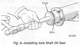
(3) Install axle shaft bearing seal using Tool C-4203 and handle C-4171, flat side of tool must be against seal, (Fig.
6) until the tool bottoms against housing flange face. This positions the seal to the proper depth beyond the end of the flange face.
(4) Lubricate bearing and lip seal. Slide axle shaft into place being careful that splines of shaft do not damage seal and properly engage with splines of differential side gears.
(5) With axle shaft in place, install the ōCö locks in recessed grooves of axle shaft, and pull outward on shaft so the ōCö locks seats in the counterbore of differential side gear.
(6) Install differential pinion shaft through case and pinions, aligning hole in shaft with lock screw hole. Install lock screw and tighten to 100 in. lbs. (11
NĢm).
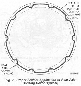
(7) Scrape any gasket material from housing cover and thoroughly clean surface with mineral spirits or equivalent and dry completely. Apply a 1/16 inch to 3/32 inch bead of MOPAR Silicone Rubber Sealant, Part No. 4318025 or equivalent (Fig.
7) along the bolt circle of the cover.
Allow sealant to cure while cleaning carrier gasket flange with mineral spirits or equivalent. Dry surface completely. Install cover on axle and torque cover screws to 35 ft. lbs. (47
NĢm). Beneath one of the cover screws, install the ratio identification tag.
If for any reason the cover is not installed within 20 minutes after applying sealant, old sealant should be removed and a new bead installed.
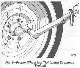
(8) Install brake drum and wheel and tire assembly, and tighten wheel nuts in the proper sequence (Fig.
8). Tighten wheel nuts to 85 ft. lbs. (115 NĢm).
(9) Adjust vehicle into a level position.
(10) Remove filler plug and fill with lubricant (see specifications for capacity). Replace filler plug.
(11) Lower vehicle and test operation of brake and axle assembly.
REAR AXLE ASSEMBLY (back to CONTENTS)
It is not necessary to remove the complete axle assembly for any normal repairs. However, if the housing is damaged, the axle assembly may be removed and installed using the following procedure.
Removal
(back to CONTENTS)
(1) Raise vehicle to a comfortable working height that will permit floor stands to be installed at front of rear springs.
(2) Block brake pedal in the ōupö position.
(3) Drain lubricant from differential housing.
(4) Loosen and remove rear wheels. Do not remove drum retaining spring clips or brake drums.
(5) Disconnect hydraulic brake lines at wheel cylinders and cap fittings to prevent loss of brake fluid.
(6) Disconnect parking brake cables.
To maintain proper drive line balance when reassembling, make scribe marks on the propeller shaft universal joint and the pinion flange before removal.
(7) Disconnect propeller shaft at differential pinion flange and secure in a near horizontal position to prevent damage to front universal joint.
(8) Remove shock absorbers from spring plate studs and loosen rear spring ōUö bolt nuts and remove ōUö bolts.
(9) Remove axle assembly from vehicle.
(10) Using a suitable cleaning solvent wash and clean the outer surface of axle assembly and blow dry with compressed air.
Installation
(back to CONTENTS)
(1) With body supported at front of rear springs, position rear axle assembly spring pads over the spring center bolts.
(2) Install spring ōUö bolts and tighten nuts to 45 ft. lbs. (61 NĢm) and install shock absorbers on spring plate studs.
(3) Connect parking brake cables.
(4) Connect hydraulic brake lines at wheel cylinders, adjust brakes and bleed brakes.
(5) Insert hydraulic brake lines into clips.
(6) Install brake tee bolt and torque to 125 in. lbs. (14 NĢm).
(7) Install rear universal joint of propeller shaft in same position as removed (match scribe marks on propeller shaft universal joint and pinion flange). Tighten universal joint clamps to 170 in. lbs. (19
NĢm).
(8) Install brake drum and wheel and tire assembly, and tighten wheel nuts in the proper sequence (Fig.
8). Tighten wheel nuts to 85 ft. lbs. (115 NĢm).
(9) Fill differential as specified with MOPAR Hypoid Lubricant Part Number 4318058 or equivalent. Install filler plug.
DIFFERENTIAL RECONDITIONING (back to CONTENTS)
It is not necessary to remove the complete axle assembly to recondition the differential.
CAUTION: Under no circumstances should rear axle bearing cones, cups, bores or journals be subjected to heating with a torch, beating with a hammer or any other abnormal abuse, as permanent damage may result. Proper removers and installers are available and their use is highly recommended.
Removal and Disassembly
(back to CONTENTS)
(1) Block brake pedal in the up position.
(2) Raise vehicle on hoist. Support body at front of rear springs and lower rear hoist.
(3) Remove rear wheels and brake drums.
(4) To maintain proper drive line balance when reassembling, make scribe marks on the propeller shaft universal joint and the pinion flange before removal. Disconnect propeller shaft at differential yoke and secure in a near horizontal position to prevent damage to front universal joint.
(5) Loosen and remove housing cover screws, and remove cover to drain lubricant.
(6) Using a suitable cleaning solvent wash and clean inside the axle housing and differential case and drive assembly.
(7) Turn differential case to make differential pinion lock screw accessible and remove lock screw and pinion shaft. Push both axle shafts toward center of vehicle and remove ōCö locks from recessed groove of axle shaft. Reinstall pinion shaft and lock screw.
(8) Remove axle shafts from housing being careful not to damage the axle shaft bearing which will remain in the housing.
Side play and runout checks taken during disassembly will be very useful in reassembly.
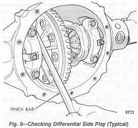
(9) Measure for differential side play. Position a screwdriver or pinch bar between left side of axle housing and differential case flange, then using a prying motion determine if side play is present.
There should be no side play. (Fig. 9).
Side play resulting from bearing cones becoming loose on differential case hubs requires replacement of case. Otherwise, use threaded adjuster to remove side play for check of drive gear run out.
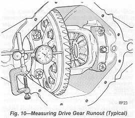
(10) In preparing to measure drive gear runout on differential case, (provided no side play was found) mount a dial indicator Tool C-3339 on pilot stud C-3288-B, and load the indicator stem slightly when plunger is at right angles to back face of drive gear (Fig.
10).
(11) Measure drive gear runout by turning drive gear several complete revolutions and reading dial indicator. Mark drive gear and differential case at point of maximum runout. The marking of differential case will be very useful later in checking differential case runout. Total indicator reading should be no more than .005 inch. If runout exceeds .005 inch the differential case may be damaged. A test for case runout will be described later.
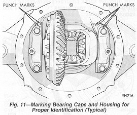
(12) Mark axle housing and differential bearing caps for proper relocation during reassembly (Fig.
11).
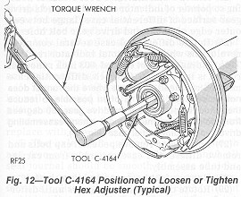
(13) Remove adjuster lock from each bearing cap. Loosen but do not remove bearing caps.
(14) Insert Tool C-4164 through axle tube on each side and loosen hex adjuster (Fig.
12).
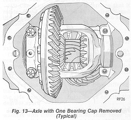
(15) Place one hand on differential assembly to hold it in position. Using extreme caution remove bearing caps, adjusters and differential assembly (Fig.
13). Differential bearing cups must be kept with their respective bearing cones. On 8-1/4 inch axles the threaded adjusters must also be kept with their respective bearings. On 7-1/4 inch axles the adjusters will remain in the housing.
(16) Using an inch-pound torque wrench, measure pinion bearing preload by rotating the pinion flange slowly with the torque wrench, record maximum value. Remove drive pinion nut and washer. Using Tool C-452 and holding Tool C-3281 remove drive pinion flange (Fig.
14).
(17) Using Tool C-748 or a screwdriver tip and hammer, remove the drive pinion oil seal from carrier casting and discard.
(18) To remove drive pinion or front pinion bearing cone, the pinion stem must be driven rearward out of the bearing.
This will result in damage to bearing rollers and cups and both bearing cone and cup must be replaced with new parts. Discard collapsible spacer.
(19) Using Tool C-4306 removers and C-4171 handle, remove front and rear bearing cups from housing.
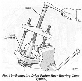
(20) Remove rear pinion bearing cone from drive pinion stem. On 7-1/4 inch axles use Tool C-293-PA and C-293-40 adapters. On 8-1/4 inch axles use Tool C-293-PA and C-293-42 adapters. Care must be taken to insure that the adapters are located so as not to pull on bearing cage
(Fig. 15). Remove shim from drive pinion stem and record thickness.
(21) Mount differential case and ring gear assembly in a vise equipped with soft jaws (brass).
Do not remove drive gear from case unless either the case or the gear set is to be replaced or if runout in step 11 exceeds .005 inch.
(22) Remove and discard drive gear bolts. Bolts are left hand thread. With non-metallic hammer or brass drift, tap drive gear loose from differential case pilot and remove.
(23) If drive gear runout exceeded .005 inch in step 11, differential case flange runout should be remeasured. Install differential case and respective bearing cups and adjusters in housing.
(24) Install bearing caps and bearing cap bolts. Tighten bearing cap bolts down lightly and using Tool C-4164 screw in both hex adjusters until all side play in bearings has been eliminated.
(25) Attach a dial indicator Tool C-3339 to housing so pointer of indicator squarely contacts drive gear surface of differential case flange between outer edge of flange and drive gear bolt holes.
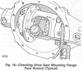
(26) Rotate differential case several complete revolutions while noting total indicator reading. This reading must not exceed .003 inch runout. If runout is in excess of .003 inch, differential case must be replaced.
In a case where the runout does not exceed .003 inch it is often possible to reduce the runout by positioning the drive gear 180 degrees from point of maximum runout when reassembling drive gear on differential case (Fig.
16).
(27) Loosen and remove pedestal cap bolts and remove differential case assembly from carrier and tube assembly.
(28) Remove lock screw and pinion shaft.
(29) Rotate differential side gears until differential pinions appear at differential case window opening and remove.
(30) Remove differential side gears and thrust washers. Remove differential case from vise.
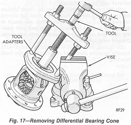
(31) Remove differential bearing cone (Fig. 17). On 7-1/4 inch axles use Tool C-293-PA and C-293-44 adapters with SP-3289 plug. On 8-1/4 inch axles use Tool C-293-PA and C-293-48 adapters with SP-3289 plug.

Cleaning and Inspection
(back to CONTENTS)
(1) Wash and clean all parts in a suitable cleaning solvent, dry with compressed air. To clean axle housing tubes, insert a stiff wire into tube, attach a clean cloth to wire at center section and withdraw from center outward.
(2) All machined contact surfaces in the axle housing and differential bearing caps should be smooth and free of any raised edges. Front and
rear pinion bearing cup bore machine surfaces should be smooth. Raised metal on shoulders of bores incurred in removal of cups should be flattened by use of a flat nosed punch.
(3) Axle shaft oil seal bores at both ends of housing should be smooth and free of rust and corrosion. This also applies to brake support plate and housing flange face surface.
(4) The axle shaft journal and axle shaft bearing rollers should be cleaned and inspected for pitting, spalling or other imperfections. If either requires replacing, discard both components and replace with new parts.
(5) The axle shaft splines should be smooth and free of excessive wear. The ax1e~ shaft oil seal journal should be smooth and free of nicks, scratches or blemishes. To remove any imperfections, polish with No. 600 crocus cloth (without reducing diameter of axle shaft oil seal surface). Use circumferential motion only.
(6) Differential bearings and front and rear pinion bearing cone and cup assemblies should have a smooth appearance with no broken or dented surfaces on rollers or roller contact surfaces. The bearing roller retainer cages must not be distorted or cracked.
When replacing bearings, always replace the cup and cone in a set only.
(7) Inspect drive gear and pinion for worn or chipped teeth or damaged attaching bolt threads. If replacement is necessary, replace both the drive gear and drive pinion as they are available in matched sets only.
(8) Inspect the pinion flange for cracks, worn splines and oil seal journal. Replace pinion flange as necessary.
(9) Inspect drive pinion bearing shim for breakage or distortion and replace if necessary.
(10) Differential side gears and pinions should have smooth teeth with a uniform contact pattern without excessive wear or broken surfaces. The differential side gear hub surfaces and thrust washer contact surfaces should be smooth and free from any scoring or metal pickup.
(11) The machined thrust washer surface areas inside the differential case should be polished and with no surface imperfections. The pinion shaft bore in differential case should be round and without excessive wear in areas of contact with either differential case or differential pinions.
The differential pinion shaft should be smooth and free of any wear. If either of the differential side gear or differential pinions require replacement, they must be replaced as a package. Under no circumstances should these components be replaced separately.
(12) Inspect axle shaft ōCö locks for signs of cracks or wear and replace if necessary.
(13) Check each adjuster to determine that it rotates freely. If adjuster binds, repair damaged threads or replace adjuster as required to allow adjusters to turn freely.
Assembly and Installation
(back to CONTENTS)
Liberally lubricate all components with rear axle lubricant.
(1) Install thrust washers on differential side gears and position gears in counterbores of differential. If assembling with new differential gears or thrust washers refer to ōDifferential Side Gear Clearance and Adjustmentö.
(2) Position thrust washers on both differential pinion gears and mesh the pinion gears with the side gears, having pinion gears exactly 180 degrees apart.
(3) Rotate side gears to align pinion gears and washers with differential pinion shaft holes in case. Install lock screw and tighten to 90 in. lbs. (10
NĢm).
(4) The contact surface of the~ drive gear and differential case flange must be clean and free of all burrs.
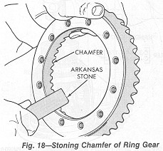
(5) On axles requiring ring gear to be installed on differential case, relieve the sharp edge of the chamfer on the inside diameter of the ring gear using an Arkansas stone (Fig.
18). This is very important, otherwise during the installation of ring gear on differential case, the sharp edge will remove metal from the pilot diameter of case, which can get imbedded between differential case flange and gear, causing ring gear not to seat properly.
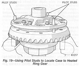
(6) Heat the ring gear with a heat lamp or by immersing the gear in a hot fluid (water or oil). The temperature should not exceed 300 degrees
Fahrenheit (149.0 degrees Celsius). DO NOT USE A TORCH. It is advantageous to use pilot studs equally spaced in three positions to align the gear to the case (Fig.
19).
(7) Using new drive gear screws (left hand threads) insert through case flange and into drive gear.
(8) Position unit between brass jaws of a vise and alternately tighten each screw to 70 ft. lbs. (95 NĢm) on all axles.
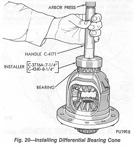
(9) Position each differential bearing cone on hub of differential case (Taper away from drive gear) and carefully install bearing cones. On 7-1/4 inch axles use Tool C-3716-A and C-4171 handle. On 8-1/4 inch axles use Tool C-4340 and C-4171 handle. An arbor press may be used in conjunction with installing Tool (Fig.
20).
CAUTION: Never exert pressure against the bearing cage, since this would damage the bearing.
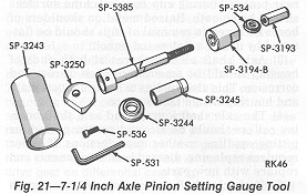
Select the proper rear axle pinion setting gauge set (Figs. 21 and
22) and proceed as follows.
(10) Start both drive pinion bearing cups into axle housing bores making sure they are not cocked.
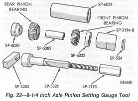
(11) On 7-1/4 inch axles assemble pinion locating spacer SP-3244 over main body of Tool SP-5385 followed by rear bearing cone. Position tool in rear axle housing, then install shaft locating sleeve SP-3245, front bearing cone, compression sleeve SP-3194-B, centralizing washer SP-534 and compression nut SP-3193.
On 8-1/4 inch axles assemble pinion locating spacer SP-6030 over main body of Tool SP-5385 followed by rear bearing cone. Position tool in rear axle housing, then install shaft locating sleeve SP-5382, front pinion bearing cone, SP-6022 washer followed by compression sleeve SP-3194-B, centralizing washer SP-534 and compression nut
SP-3193.
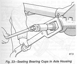
(12) While holding compression sleeve from turning with Tool C-3281, tighten nut, thereby drawing pinion bearing cups into axle housing bearing cup bores. Permit tool to turn several revolutions during tightening operation to prevent brinnelling of bearing cups or cones (Fig.
23).
The position of the drive pinion with respect to the drive gear (depth of mesh) is determined by the location of the bearing cup shoulders in the carrier and by the portion of the pinion in back of the rear bearing. A shim is located between the rear pinion bearing cone and the head of the pinion. The thickness of this shim will be determined next.
(13) Loosen tool nut SP-3193 on 7-1/4 inch and 8-1/4 inch axles. Lubricate front and rear pinion bearings with rear axle lubricant. Retighten nut to produce 15 to 25 in. lbs. (1 to 3 NĢm) of rotating torque. Rotate pinion several complete revolutions to align bearing rollers.
(14) On 7-1/4 inch axles install gauge block SP-3250 on end of main body SP-5385, install cap screw SP-536 and tighten securely with SP-531 wrench.
On 8-1/4 inch axles install gauge block SP5383 on end of main body SP-5385, install cap screw SP-536 and tighten securely with SP-531 wrench.
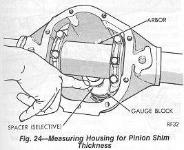
(15) On 7-1/4 inch axles position crossbore arbor SP-3243 in axle housing differential bearing seats.
On 8-1/4 inch axles position crossbore arbor SP-6029 in axle housing differential bearing seats.
Center the arbor so that an approximate equal distance is maintained at both ends. Position bearing caps and attaching bolts on carrier pedestals and insert a piece of .002 inch shim stock between arbor and each cap. Tighten cap bolts to 10 ft. lbs. (14
NĢm).
(16) Select rear pinion bearing mounting shim which will fit between crossbore arbor and gauge block (Fig.
24). This fit must be snug but not too tight (similar to the pull of a feeler gauge). Shims are available in .001 inch increments from .020 inch to .038 inch.
(17) Read the markings on the end of the pinion head (-0, -1, -2, +1, +2, etc.). When marking is
-(minus), add that amount to the thickness of shims selected in step (16). When the marking is + (plus), subtract that amount. Treat other pinion markings in a similar manner.
(18) Remove the tool arbor and tool from axle housing.
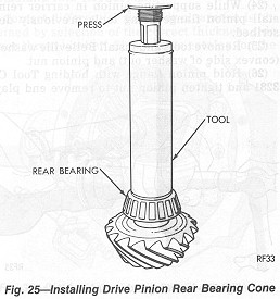
(19) Position shim selected in step (16) on pinion followed by rear pinion bearing cone (make certain that pinion head contact surface, bearing cone and shim are clean and free from foreign particles). Using Tool C-3717 for 7-1/4 inch axles or Tool C-4040 for 8-1/4 inch axles, press bearing on pinion stem. An arbor press may be used in conjunction with tool (Fig.
25).
(20) Lubricate front and rear pinion bearing cones with rear axle lubricant.
(21) Insert drive pinion and bearing assembly through axle housing. Install new collapsible spacer over pinion stem. Position front pinion bearing cone over pinion stem.
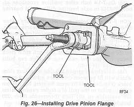
Install pinion flange using Tool C-3718 and holding Tool C-3281 (Fig. 26). This is necessary in order to properly install front pinion bearing cone on pinion stem due to interference fit.
CAUTION: During installation of front pinion bearing cone, be careful not to collapse spacer.
(22) Remove tool and flange from pinion stem.
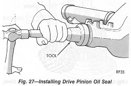
(23) Install drive pinion oil seal.
On 7-1/4 inch axles use Tool C-4002 or C-3719.
On 8-1/4 inch axles use Tool C-4076.
Seal is properly installed when seal flange contacts housing flange face (Fig. 27). Outside diameter of seal is precoated with a special sealer so no sealing compound is required.
(24) While supporting pinion in carrier reinstall pinion flange using tools previously described.
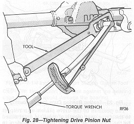
(25) Remove tools and install Belleville washer (convex side of washer out) and pinion nut.
(26) Hold pinion flange with holding Tool C3281 and tighten pinion nut to remove end play
in pinion, while rotating the pinion to insure proper bearing roller seating (Fig.
28).
(27) Remove holding tool and rotate pinion several complete revolutions in both directions to permit bearing rollers to seat.
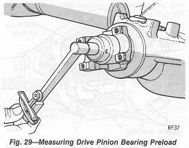
(28) Tighten pinion nut to 210 ft. lbs. (284 NĢm) and measure pinion bearing preload by rotating pinion using an inch-pound torque wrench. The correct bearing preload specifications are 15 to 30 in. lbs. (1 to 3 Nm) for 7-1/4 inch axles and 20 to 35 in. lbs. (2 to 4 NĢm) for 8-1/4 inch axles for new bearings with the pinion nut tightened to 210 ft. lbs. (285
NĢm) minimum (Fig. 28, 29). If when rebuilding the axle and the
original rear pinion bearing and a new front pinion bearing are used, the correct bearing preload is 10 in. lbs. (1
NĢm) more than the reading taken at time of tear down with a minimum of 210 ft. lbs. (285 NĢm) of torque on the pinion nut. If correct
preload cannot be obtained at 210 ft. lbs. (285 NĢm), continue tightening pinion nut in small increments and checking until proper preload is obtained. Bearing preload should be uniform during complete revolution. A preload reading that varies during rotation indicates a binding condition which must be corrected. The assembly is unacceptable if final pinion nut torque is below 210 ft. lbs. (285
NĢm) or pinion bearing preload is not within specifications.
Under no circumstances should the pinion nut be backed off to lessen pinion bearings preload. If the desired preload is exceeded a new collapsible spacer must be installed and nut retightened until proper preload is obtained.
(29) Coat differential bearing cones, cups and adjusters with axle lubricant. Carefully position differential assembly complete with bearing cups into housing.
(30) Install differential bearing caps on their respective sides, using marks made at disassembly.
(31) Install bearing cap bolts. Tighten top bolts to 10 ft. lbs. (14 Nm). Tighten bottom bolts only finger tight until head is just seated on bearing cap.
DIFFERENTIAL BEARING PRELOAD AND DRIVE GEAR BACKLASH (back to CONTENTS)
There are two precautions which must be observed when adjusting differential bearing preload and drive gear backlash. (A) Permissible backlash variation is .003 inch, for example, if the backlash is .006 inch at the minimum point, it may be .009 at the maximum point. This variation would be permissible runout. It is therefore important to index the gears so that the same teeth are engaged during all backlash measurements. (B) It is also important to maintain specified adjuster torque to obtain accurate differential bearing preload and drive gear backlash settings. Excessive torque will introduce high bearing load and cause premature bearing failures. Inadequate torque will not support the drive gear properly and may lead to free play of the differential assembly and excessive drive gear noise. Differential bearing cups will not always move directly with the adjusters, therefore to insure accurate adjustment changes and to maintain gear mesh index, bearings must be seated by oscillating drive pinion a half turn in each direction five to ten times each time adjusters are moved.
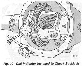
(1) Using Tool C-4164 turn each hex adjuster in (Fig. 12) until bearing free play is eliminated with some drive gear backlash (approximately .010 inch) existing between drive gear and pinion. Seat rollers per note above.
(2) Install dial indicator Tool C-3339 (Fig. 30)
and position contact point against drive side of gear tooth. To find point of minimum backlash, check backlash at 4 positions at approximately 90 degree intervals around drive gear. Rotate gear to position of least backlash. Mark the index so that all backlash readings will be taken with the same teeth in mesh.
(3) Loosen right adjuster and tighten left adjuster until the backlash is .003 to .004 inch with each adjuster tightened to 10 ft. lbs. (14
NĢm). Again seat bearings per note. Tighten differential bearing cap bolts to 45 ft. lbs. (61
NĢm) on 7-1/4 inch axles, 100 ft. lbs. (136 NĢm) on 8-1/4 inch axles. Using Tool C-4164 tighten right hex adjuster to 70 ft. lbs. (95
NĢm). Again seat bearings per note. Continue to tighten right adjuster and seat rollers until torque remains constant at 70 ft. lbs. (95 Nm). Measure backlash. If backlash does not measure between .003 to .006 inch on 7-1/4 inch axles and .005 to .008 on 8-1/4 inch axles, increase torque on right adjuster and seat bearings per note until correct backlash is obtained. Tighten left adjuster to 70 ft. lbs. (95
NĢm). Seat bearings per note until torque remains constant. If all previous steps have been properly performed, initial reading on left adjuster will be approximately 70 ft. lbs. (95 N.m). If it is substantially less, complete procedure must be repeated.
(4) After adjustments are completed, install adjuster locks. Be sure lock teeth on 7-1/4 inch axles are engaged in adjuster threads and lock finger is engaged in adjuster hole on 8-1/4 inch axles. Tighten lock screws to 90 in. lbs.(10 Nm).
DIFFERENTIAL SIDE GEAR CLEARANCE CHECKING AND ADJUSTMENT (back to CONTENTS)
Correct differential side gear clearance is obtained by selection of the correct thickness side gear thrust washer. Check parts catalog for the
applicable side gear thrust washer package required. When measuring side gear clearance treat each gear independently. It is possible for one side to have an acceptable clearance and for the other side to require servicing. In situations where you find it necessary to replace a side gear, install two new ones as a matching set.
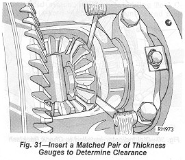
(1) With the axle shaft and ōCö locks in place, measure the clearances behind each side gear by inserting a matched pair of gauges on opposite sides of the hub (Fig. 31).
(2) If you measure .005ö clearance, or less, see if the axle shaft on that side is contacting the pinion shaft. Do this with the gauges still in place behind the side gear. If the axle shaft does not contact the pinion shaft, the side gear fit is acceptable on that side. Repeat for other side.
(3) If you measured more than .005ö clearance in step 1 and the axle shaft does not contact the differential pinion shaft, then record the side gear clearance. Remove the thrust washer and measure itÆs thickness with a micrometer. Add the washer thickness to the side gear clearance you recorded. The sum of the two numbers will tell you which replacement washer to install. For example, if you find .007ö side gear clearance, and measure thrust washer thickness at .033ö the total is .040ö. Install the thickest thrust washer from the service package that does not exceed the total above. In this case you would install the .037ö washer from the service package, since the next larger size .042ö would be too thick. When re-assembled, side clearance should now be .004ö.
(4) In some cases the axle shaft will run up against the pinion shaft when feeler gauges are inserted behind the side gear. When this occurs, the ōCö lock on the axle shaft prohibits the side gear from moving inward any farther. To find the total side gear clearance, measure the clearance again with the ōCö lock out. Record your
measurement with the ōCö locks in place.
Remove the ōCö lock on the side (or sides) having no axle shaft end play. While you have the differential apart, use a micrometer to measure the thrust washer thickness. Record your measurement and place the thrust washer back behind the side gear. Assemble the differential without the ōCö lock installed and measure the side gear clearance again.
If the clearance changes less than .012 inch with the ōCö locks removed, add the side gear clearance you recorded (when the ōCö lock was in place) to the thrust washer thickness you measured with the micrometer. The total will help you determine which thrust washer to install. For example, if the clearance is .006 inch with the ōCö lock in and .015 inch with the ōCö lock removed, the change is .009 inch, less than .012 inch. So add .006 inch (the clearance with the ōCö lock in place) to the thrust washer thickness; for example .032 inch. Your total is .038 inch. The closet thrust washer not exceeding .038 inch is .037 inch.
If the clearance increases more than .012 inch with the ōCö lock removed, you need to replace both side gears and repeat the measurement tests.
If side gear clearance still exceeds .012 inch when using new side gears and the thickest thrust washers from the service package, then the differential case must be replaced.
GEAR TOOTH CONTACT PATTERN (back to CONTENTS)
(1) Apply a thin coat of Hydrated Ferric Oxide, commonly known as Yellow Oxide of Iron, or equivalent to both the drive and coast side of the drive gear teeth. Rotate drive gear one complete revolution in both directions while load is being applied with a round bar or screwdriver between the carrier casting and differential case flange. This action will leave a distinct contact pattern on both the drive and coast side of the
drive gear teeth.
The gear tooth contact pattern will disclose whether the correct rear pinion bearing mounting shim has been installed and the drive gear backlash set properly. Backlash between the drive gear and pinion must be maintained within the specified limits until correct tooth contact pattern is obtained.
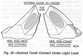
(2) Observe the contact pattern on the drive gear teeth and compare with those in Figs.
32, 33 and
35 to determine if pattern is properly located. With pinion depth of mesh and gear backlash set properly, your contact pattern should resemble that in Fig.
32. Notice that the correct contact pattern is well centered on both drive and coast sides of the teeth. When tooth contact patterns are obtained by hand, they are apt to be rather small. Under the actual operating load, however, the contact area increases.
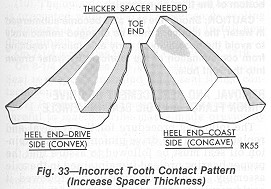
(3) If after observing the contact pattern you find it resembles that in Fig.
33, the drive pinion is too far away from centerline of the ring gear, the contact pattern will appear high on the heel on drive side and high on toe on coast side. To
correct this type tooth contact pattern, increase the thickness of shim located between the drive pinion and rear pinion bearing cone (Fig.
34), which will cause the high heel contact on drive side to lower and move toward the toe; the high toe contact on coast side will lower and move toward the heel.
(4) If after observing the contact pattern you find it resembles that in Fig.
35, the drive pinion is too close to the centerline of the ring gear, the pattern will appear low on the toe on drive side and low heel contact on coast side. To correct this type tooth contact pattern, decrease the thickness of shim located between the drive pinion and rear pinion bearing cone (Fig.
36), which will cause the low toe contact on drive side to raise and move toward the heel; low heel contact on coast side will raise and move toward the toe.
(5) When correct tooth contact pattern is obtained, install propeller shaft, aligning scribe marks made during disassembly. Tighten clamp screws to 170 in. lbs. (19
NĢm).
(6) Install new axle shaft bearing seals with Tool C-4203 and handle C-4171, flat side of tool. Must be against seal (Fig.
6). Carefully slide axle shafts in place, install the ōCö locks in. recessed grooves of axle shafts, pull outward on each shaft
so ōCö locks seat in counterbore of differential side gear.
(7) Install differential pinion shaft through case and pinions, aligning hole in shaft with lock screw hole. Install lock screw and tighten to 100 in. lbs. (11
NĢm).
(8) Scrape any gasket material from housing cover and thoroughly clean surface with mineral spirits or equivalent and dry completely. Apply a 1/16 inch to 3/32 inch bead of MOPAR Silicone Rubber
Sealant, Part No. 4318025 or equivalent (Fig. 7) along the bolt circle of the cover.
Allow sealant to cure while cleaning carrier gasket flange with mineral spirits or equivalent. Dry surface completely. Install cover on axle and torque cover screws to 35 ft. lbs. (47
NĢm). Beneath one of the cover screws, install the ratio identification tag.
If for any reason cover is not installed within 20 minutes after applying sealant, old sealant should be removed and new bead installed.
(9) Install brake drums and wheel and tire assemblies. Tighten wheel nuts to 85 ft. lbs. (115
NĢm) in proper sequence (Fig. 8). Remove block from brake pedal.
(10) Adjust vehicle to a level position.
(11) Remove filler plug and fill rear axle with lubricant (see specifications for capacity). Replace filler plug.
(12) Lower vehicle and test operation of brake and axle assembly.
LUBRICATION (back to CONTENTS)
Multi-Purpose Gear Lubricant, as defined by the American Petroleum Institute GL-5 should be used in all rear axles with conventional differentials; MOPAR Hypoid Lubricant, Part No. 4318058 is an oil of this type and is recommended or equivalent.
Fluid Level Check
For normal passenger car service, period fluid level checks are not required. At each engine oil change however, a fluid level check is recommended.
When this check is performed with the car in a level position, supported by the suspension, the fluid level should be between the bottom of the filler plug opening and a point 1/4 inch (6/4 mm) below the filler plug opening.
If the fluid level check is performed with the vehicle on a frame contact type hoist, with the axle hanging free, the fluid level should not be lower than the bottom of the filler plug opening.
CAUTION: Should the rear axle become submerged in water, the lubricant must be changed immediately to avoid the possibility of early axle failure resulting from contamination of the lubricant by water drawn into the vent hole.
REMOVAL AND REPLACEMENT OF DRIVE PINION FLANGE AND OIL SEAL IN VEHICLE (back to CONTENTS)
The following procedure for the removal and replacement of the drive pinion flange and pinion oil seal must be followed to assure that the proper bearing preload is maintained in the axle assembly. If this procedure is not followed it could result in a premature failure of the axle.
(1) Raise vehicle on hoist and make scribe marks on propeller shaft, shaft universal joint, drive pinion flange and end of pinion stem.
(2) Disconnect propeller shaft at pinion flange and secure in an upright position to prevent damage to front universal joint.
(3) Remove the rear wheels and brake drums to prevent any drag or a possible false preload reading could occur.
(4) Using inch-pound torque wrench C-685-A measure pinion bearing preload by rotating pinion with handle of wrench floating, read the torque while wrench is moving through several complete revolutions and record.
This operation is very important because preload must be carefully reset when reassembling.
(5) With Tool C-3281 hold pinion flange and remove drive pinion nut and Belleville washer.
(6) Install pinion flange remover Tool C-452 and remove flange. Lower rear of vehicle to prevent lubrication leakage.
(7) Using a screwdriver and hammer, remove the pinion oil seal from the carrier and clean the oil seal seat.
(8) Check splines on pinion shaft stem to be sure they are free of burrs or are not worn badly. If burrs are evident remove them using crocus cloth by working in a rotational motion. Wipe the pinion stem clean.
(9) Inspect the pinion flange for cracks, worn splines, and oil seal journal. Replace the pinion flange as necessary.
(10) The outside diameter of the seal assembly is precoated with a special sealer so no sealing compound is required for installing. Install new drive pinion oil seal.
On 7-1/4 inch axles use Tool C-4002 or C-3719.
On 8-1/4 inch axles use Tool C-4076.
Seal is properly installed when seal flange contacts housing flange face.
(11) Position pinion flange on pinion stem being careful to match scribe marks made previously before removal.
(12) Install pinion flange using Tool C-3718 and holding Tool C-3281.
(13) Remove tool and install Belleville washer (convex side of washer out) and pinion nut.
(14) Hold pinion flange with holding Tool C-3281 and tighten pinion nut to 210 ft. lbs. (285 Nm). Rotate pinion several complete revolutions to assure that bearing rollers are properly seated. Using an inch-pound torque wrench C-685-A measure pinion bearing preload. Continue tightening pinion nut and checkingpreload until preload is at the original established setting you found in Step 4. Under no circumstances should the preload be more than 10 in. lbs. (1
NĢm) over the
established setting found at time of checking in Step 4 of procedure.
Bearing preload should be uniform during a complete revolution. A preload reading that varies during rotation indicates a binding condition which has to be corrected. The assembly is unacceptable if final pinion nut torque is below 210 ft. lbs. (285
NĢm) or pinion bearing preload is not within the correct specifications.
Caution: Under no circumstances should the pinion nut be backed off to lessen pinion bearing preload.
If the desired preload is exceeded a new collapsible spacer must be installed and nut retightened until proper preload is obtained. In addition, the universal joint flange must never be hammered on or power tools used.
(15) Install propeller shaft (match scribe marks on propeller shaft universal joint and pinion flange). Tighten clamp screws to 170 in. lbs. (19
NĢm).
(16) Install the rear brake drums and wheels and tighten nuts to 85 ft. lbs. (115
NĢm).
(17) Raise the vehicle to a level position so axle assembly is at correct running position and check lubricant level. Add the correct type of lubricant required to bring the lubricant to proper level.
Sure Grip info
Sure Grip info