As the gears operate, they produce friction and heat. This makes the gears expand, reducing the clearance between the meshing teeth of the gears. Without backlash, the ring and pinion teeth can jam into each other and fail in a very short period of time. However, too much ring and pinion backlash can cause gear noise (whirring, roaring, or clunking).
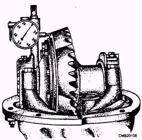
Figure 5-20.- Measuring ring gear runout.
To measure ring and pinion backlash, position a dial indicator stem on one of the ring gear teeth. Then, while holding the pinion gear STATIONARY, wiggle the ring gear back and forth. Indicator needle movement will equal gear backlash. Compare your measurements to the manufacturer's specifications and adjust as needed.
Backlash adjustment can be made by adjusting nuts or by moving shims from one side to the other. To increase backlash, move the ring gear away from the pinion gear. To decrease backlash, move the ring gear towards the pinion gear.
RING AND PINION TOOTH CONTACT PATTERN.- The ring and pinion tooth contact pattern is used to double-check ring and pinion adjustment.
To check the accuracy of your adjustments, coat the ring gear teeth with a thin coat of red lead, white grease, hydrated ferric oxide (yellow oxide or iron), or Prussian blue. Turn the ring gear one way and then the other to rub the teeth together, producing a contact pattern on the teeth. Carefully note the contact pattern that shows up on the teeth where the substance used has been wiped off.
A good contact pattern is one located in the center of the gear teeth (fig. 5-21). Figure 5-21 shows several ring and pinion gear contact patterns. Study each and note the suggested correction for the faulty contact. Note the names of the areas on the ring gear. These include the following:
TOE (narrow part of the gear tooth)
HEEL (wide part of the gear tooth)
DRIVE SIDE (convex side of the gear tooth)
COAST SIDE (concave side of the gear tooth)
When used gears are adjusted properly, the contact pattern will vary from that of new gears. The important thing to keep in mind with used gears is that the pattern should be closer to the toe than the heel of the tooth, as shown in figure 5-21. Notice that the ideal tooth pattern on new teeth is uniform on both sides, whereas the used gear indicates considerably more contact on the coasting side.
Once you have obtained the proper adjustment on the ring and pinion, bolt the carrier housing in place. Make sure you use a new gasket. Tighten the bolts according to the manufacturer's specifications to prevent them from working loose. Reinstall the axle shafts and new gaskets. Reconnect the drive shaft and fill the axle housing with the proper lubricant.
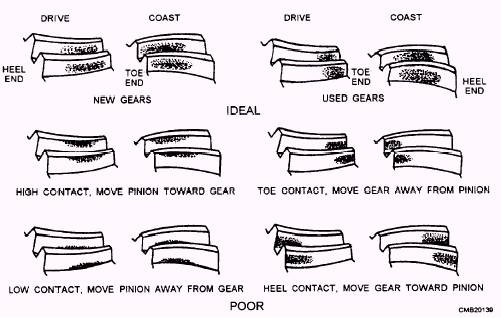
Figure 5-21 - Tooth contact patterns