Mopar Performance Electronic Ignition Kit Instructions
PAGE 1 of 10
Instruction Sheet DCF-194CC MOPAR PERFORMANCE ELECTRONIC IGNITION KIT
with
VACUUM ADVANCE DISTRIBUTOR
Part Numbers P3690426, P3690427 & P3690428
This package includes a vacuum advance distributor, wiring harness, electronic control unit (ECU), ballast resistor and wiring connectors. Installation is simple and can be accomplished with basic automotive tools. It is suggested to read through instructions at least once before beginning the installation. These instructions are divided various sections. The first section pertains to all installations. The next four sections pertain to the style of ignition system being replaced: Point Type (used up to the early 70's), Chrysler Electronic (used from the early to late 70's), Lean Burn/Spark Control Computer (used from mid '70's to the late 80's), and Logic Computer Controlled (used with all TBI fuel injected vehicles). The fifth and sixth sections deal with Start Up and Tuning. A short Trouble Shooting section and additional sections on wiring Street Rods and wiring vehicles without existing wiring harnesses are included also. Tools required for each installation are listed at the beginning of each section. If any troubles arise, call the Mopar Performance Tech Hotline at (248) 969-1690.
NOTE: THE CHRYSLER FUEL INJECTION SYSTEM REQUIRES A SIGNAL GENERATED BY THE ORIGINAL EQUIPMENT DISTRIBUTOR. TO INSTALL THIS KIT, THE FUEL INJECTION SYSTEM MUST BE ELIMINATED. THIS IGNITION KIT WILL NOT OPERATE THE FUEL INJECTION SYSTEM USED ON CHRYSLER CORPORATION VEHICLES.
FOR ALL INSTALLATIONS:
Additional Tools Required: Distributor wrench, .008" brass feeler gauge
1. Disconnect the negative (ground) battery cable.
2. At the coil, disconnect the wire leading from the negative side of the coil to the distributor.
3. Note the location of the number one spark plug wire on the
distributor. Disconnect the spark plug wires from the spark plugs and coil. Remove the wires from any wire looms or retainers.
4. Disconnect the distributor cap hold down clips, remove the distributor cap and spark plug wires together. Set them aside.
5. Note the location of the distributor rotor. Carefully mark the location where the metal end of the rotor is pointing by placing a piece of tape on the engine or firewall, .
6. If the distributor being replaced is equipped with a vacuum advance canister, note the direction the vacuum advance canister is pointing and disconnect the vacuum advance hose.
7. Remove the distributor hold down bolt and hold down clamp.
8. Clean off the area around the distributor opening.
9. Carefully remove the distributor from the engine. Rotating the distributor back and forth usually helps.
10. Disconnect the distributor hold down clips on the MP distributor and remove the distributor cap.
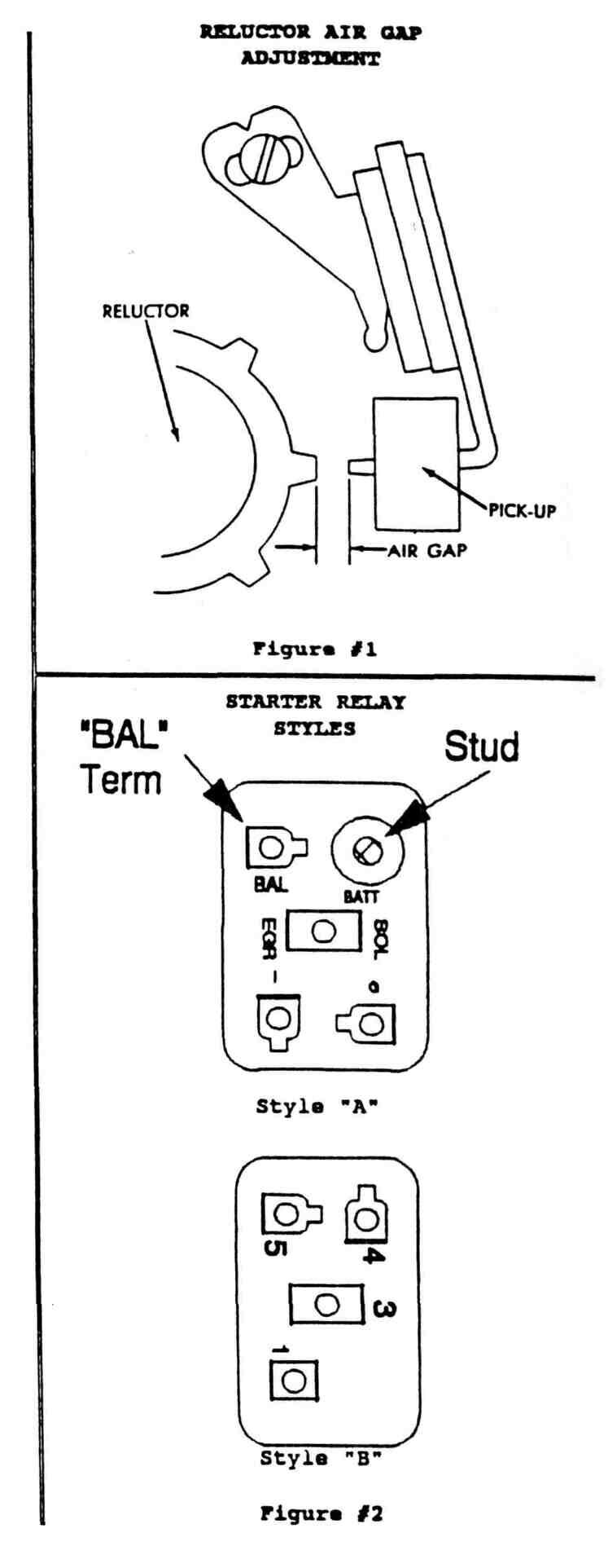
11. Check the air gap between the distributor pickup and the reluctor (see Figure #1 on page 8). The air gap specification is .008". This should be checked with a brass (non-magnetic) feeler gauge. Set the air gap if required. Check all 8 gaps!
12. Rotate the distributor shaft by hand. It should rotate freely, but it is normal to feel "pulsations" as the reluctor prongs pass the pick up.
13. Check to make sure the distributor's 0-ring seal is in place and lightly coat the 0-ring with oil.
14. If your old distributor was equipped with vacuum advance, hold the new distributor so the vacuum advance canister is in the same position as it was on the old distributor, as noted in step #6, and carefully set the new distributor most of the way into the block. If your old distributor was not equipped with vacuum advance, set the new distributor in the block so the distributor can be rotated at least 45 degrees without the vacuum advance canister hitting anything.
15. Turn the rotor until it points at the tape mark you made in step #5. Carefully push, DO NOT FORCE, the distributor down into the block. It may help to slightly rotate the distributor back and forth while wiggling the rotor. The distributor should meet the block's surface.
16. Reinstall the distributor hold down bolt and clamp. Just snug the bolt, do not tighten. The distributor should still be able to be rotated with a little effort.
17. Reinstall the new distributor cap.
18. Proceed to the section pertaining to the type of ignition system being replaced.
REPLACING POINT TYPE IGNITION:
Additional Tools Required: Electric drill, wire cutter/stripper, one 12 gauge solderless electrical connector, 12 volt test light, and electrical tape.
1. Choose a suitable location for the Electronic Control Unit (ECU). The ECU must be bolted down, make sure the mounting location selected is a flat surface and can be drilled through. The ECU should be located away from the exhaust system, in the coolest place possible. Recommended locations are: the corners of the firewall; the inner fenderwell; the radiator support panel/grill area; or under the dashboard, inside the car.
2. Using the new wiring harness provided with the ignition kit, connect the two wire distributor wiring plug into the similar plug on the distributor. Place the five wire ECU plug at the location chosen for mounting the ECU. Make sure the new wiring harness can be routed from the distributor to the ECU while avoiding exhaust parts and sharp edges. Try to follow the cars existing wiring harness if possible.
3. Once it is confirmed that the wiring harness will reach the ECU mounting location, use the ECU as a guide and mark the bolt holes on each side of the ECU.
4. The attaching hardware to mount the ECU must be provided, it is not included in the kit. Either nuts and bolts or sheet metal screws can be used. If using sheet metal screws, make sure the sharp points will not damage or contact anything on the opposite side of the mounting location. If using nuts and bolts, make sure the nuts can be reached on the opposite side of the mounting location to tighten them. Drill holes to mount the ECU, making sure they are the correct size for the bolts or screws being used. Mount the ECU and tighten securely.
5. Connect the five way plug to the ECU and route the distributor wires so they will be protected from harm. If possible, run
PAGE 2 of 10
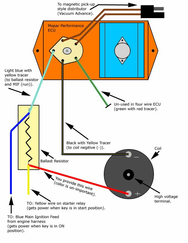
them through existing looms and/or use plastic ties to secure them to the existing wiring harness. Identify the three loose wires of the wiring harness. There will be a black wire (with a yellow tracer or line), a blue wire (with a yellow tracer) and a green wire (with a red tracer).
7. The green wire is not used and should be cut off at the point it comes out of the wiring harness's protective wrapping. Special note - in the newer wiring harnesses, this unused wire has been omitted.
8. The black wire should be routed to the negative side of the ignition coil. Avoid the exhaust manifolds and sharp edges. Follow the cars existing wiring harness, if possible. Once suitably routed to the coil, cut the black wire to remove any excess. Strip the insulation off the last 1/4 inch of the wire. Crimp the round eyelet provided in the ignition kit to the exposed wire. Attach the black wire to the negative side of the ignition coil.
9. Route the blue wire to the ballast resistor. Avoid the exhaust manifolds and sharp edges, follow existing wiring harnesses if possible.
10. Disconnect the wires from both ends of the original ballast resistor. Remove the old ballast resistor and install the new ballast resistor in its place. Do not reconnect the wires.
11. Temporarily reconnect the negative battery cable. Make sure neither of the ballast resistor wires are touching any metal and turn the ignition key to the "on" position. Do not turn to the "start" position. Use your 12 volt tester to determine which one of two connectors you removed from the ballast resistor is "hot" or has power. This is the "feed" side.
12. Turn the ignition key off and disconnect the negative battery cable.
13. The blue wire of the new wiring harness must be spliced into the "feed" connector identified in step #11. The feed connector must still be able to be plugged onto the ballast resistor, a splice must be made. The feed connector can contain from one to three wires in the original wiring harness. The easiest method of splicing these wires is to clip off the original female spade connector, strip 1/4 to 3/8 inch of insulation off the old wire(s) and the new blue wire, then crimp all of the wires back into a new female spade connector. Other methods of splicing are acceptable, but this one seems to work the best. Use electrical tape to seal the connection.
14. Reconnect both wiring connectors to the ballast resistor.
15. Proceed to "Basic Start Up and Adjustment"
REPLACING ELECTRONIC IGNITION: Additional Tools Required: None.
1. Connect the two wire connector to the new distributor.
2. Disconnect the five wire connector from the production Electronic Control Unit (ECU). Unbolt the old ECU and replace it with the new performance ECU.
Note: The ECUs used from 1972 through 1979 had five pins or connections. The new performance ECU has only four pins.
3. Reconnect the five wire connecter.
4. Remove the two connectors from the ballast resistor. Note that in each of the connectors there are two terminals. On one connector, there is usually an 18 gauge dark green wire in one terminal and a 14 gauge brown wire in the other. On the second connector, there is usually a 18 gauge light blue wire in one terminal, a 16 gauge dark blue wire in the other and an 18 gauge black wire connected from one position to the other.
5. Unbolt the old ballast resistor and install the new ballast resistor in it's place.
Note: The dual ballast resistors used from 1972 through 1979 had four terminals. The new performance single resistor has only two terminals. The two extra terminals fed the fifth pin used on the early ECUs and are not required with the performance four pin ECU.
6. On the first connector of the new ballast resistor, plug the terminal containing the 14 gauge brown wire onto one terminal of the new ballast resistor. On the second connector, plug the terminal containing the 16 gauge dark blue wire onto the other terminal of the new ballast resistor. The unused terminal on each connector will be left empty. As stated in step #5, they fed the fifth pin on the ECU and are not required on the new four pin ECU.
7. Proceed to "Basic Start Up and Adjustment"
REPLACING LEAN BURN/SPARK CONTROL COMPUTER IGNITION:
Additional Tools Required: Electric drill, wire cutter/stripper, 12 volt test light, roll of 14 gauge electrical wire, two 14 gauge
Scotchlok® electrical connectors, one 14 gauge round eyelet electrical connector, two 14 gauge female spade electrical connectors, two 12 gauge female spade electrical connectors, one 14 gauge butt connector, electrical tape.
1. Choose a suitable location for the Electronic Control Unit (ECU). The ECU must be bolted down, make sure the mounting location selected is a flat surface and can be drilled through. The ECU should be located away from the exhaust system, in the coolest place possible. Recommended locations are: the corners of the firewall; the inner fenderwell; the radiator support panel/grill area; or under the dashboard, inside the car.
2. Using, the new wiring harness provided with the ignition kit, connect the two wire distributor wiring plug into the similar plug on the distributor. Place the five wire ECU plug at the location chosen for mounting the ECU. Make sure the new wiring harness can be routed from the distributor to the ECU while avoiding exhaust parts and sharp edges. Try to follow the cars existing wiring harness.
3. Once it is confirmed that the wiring harness will reach the location, use the ECU as a guide and mark the bolt holes on each side of the ECU.
4. The attaching hardware to mount the ECU must be provided. It is not included in the kit. Either nuts and bolts or sheet metal screws can be used. If using sheet metal screws, make sure the sharp points will not damage or contact anything on the opposite side of the mounting location. If using nuts and bolts, make sure the nuts can be reached on the opposite side of the mounting location to tighten them. Drill holes to mount the ECU, making sure they are the correct size for the bolts or screws being used. Mount the ECU and tighten securely.
5. Connect the five way plug to the ECU and route the distributor wires so they will be protected from harm. If possible, run them through existing looms and/or use plastic ties to secure them to the existing wiring harness.
PAGE 3 of 10
Remove all the wires connected to the
ignition coil. If one of the existing wires is a tachometer feed wire, it may by
reconnected. All other wires are to be left off. They should be covered with
electrical tape and secured to prevent grounding out. They will not be used.
7. Identify the three loose wires of the
wiring harness. There will be a black wire (with a yellow tracer or line), a
blue wire (with a yellow tracer) and a green wire (with a red tracer).
8. The green wire is not used and should be
cut off. On newer harnesses, this un-used wire is omitted.
9. The black wire should be routed to the
negative side of the ignition coil. Avoid the exhaust manifolds and sharp edges.
Follow the cars existing wiring harness, if possible. Once suitably routed to
the coil, cut the black wire to remove any excess. Strip the insulation off the
last 1/4 inch of the wire. Crimp the round eyelet provided in the ignition kit
to the exposed wire. Attach the black wire to the negative side of the ignition
coil.
10. Choose a location to mount the ballast
resistor. Do not remove the old ballast resistor. Although the MP Ignition Kit
will use the new ballast resistor, other components of the vehicle may need the
old resistor.
11. The attaching hardware to mount the new
ballast resistor must be provided. It is not included in the kit. Either a nut
and bolt or a sheet metal screw can be used. If using a sheet metal
screw, make sure the sharp point will not damage or contact anything on the
other side of the mounting location. If using a nut and bolt, make sure the nut
be reached on the opposite side of the mounting location to tighten it. Drill a
hole to mount the ballast resistor, making sure the hole is the correct size for
the bolt or screw being used. Mount the ballast resistor and tighten. Do not
over tighten the resistor or the porcelain may crack.
12. Route the blue wire to the new ballast
resistor. Avoid the exhaust manifolds and sharp edges, follow existing wiring
harnesses if possible. Do not cut the blue wire at this time.
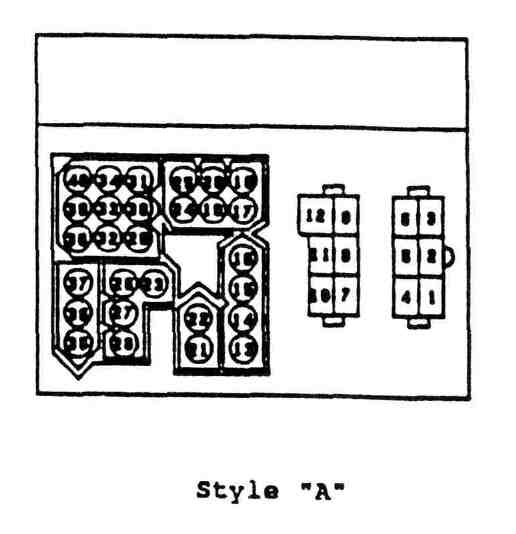
13. Locate the main ignition feed, or MIF, as
it comes through the firewall at the master disconnect connector. Refer to the
chart on page 8 and the connectors shown on page 9 to determine the style of
master disconnect connector and the location of the MIF on the vehicle being
modified.
14. Temporarily reconnect the negative battery
cable. Turn the ignition key to the "on" position. Do not turn to the
"start" position. Use a 12 volt tester to verify that the MIF found in
step #31 has power when the key is in the "on" position and has no
power when the key is in the "off" position.
15. Turn the ignition key off and disconnect
the negative battery cable.
16. Use 14 gauge wire and splice into the MIF.
Do not cut the MIF. A splice must be made, the MIF must still power many other
under hood functions. An electrical connector with the trademarked name
Scotchlok® is very useful. Slice or Scotchlok® the 14 gauge wire to the MIF,
then securely wrap the splice with electrical tape to and prevent grounding.
17. Route the spliced 14 gauge wire to the new
ballast resistor, where the blue wire of the new harness was routed in step #12.
18. Allow 3 inches of extra wire for engine
movement, then cut off both the blue wire and the new wire spliced into the MIF.
Strip 1/4 inch of the insulation from both wires. Place BOTH of the stripped
wires into ONE of the 12 gauge female spade connectors and crimp securely. Wrap
the connection with electrical tape to seal out moisture.
19. Route a 14 gauge wire from the positive
side of the ignition coil to the ballast resistor. Avoid the exhaust manifolds
and sharp edges. Follow existing wiring harnesses, if possible. Leave plenty of
extra wire and cut off the new wire by the ballast resistor. On the end of the
new wire by the ignition coil, strip the insulation from 1/4 inch of the new
wire. Crimp the 14 gauge round eyelet onto the new wire and connect it to the
positive side of the coil. Leave the other end by the ballast resistor.
20. Locate the starter relay. It is usually
located on the left (drivers) side shock housing or on the left side of the main
bulkhead (firewall). A multiple wire connector will be connected to the starter
relay. Carefully unplug the multiple wire connector. Refer to Figure #2 on page
8 to determine the style of starter relay. Follow the instructions according to
your style of starter relay. (Note: 1988 and newer cars/full size trucks/vans
and 1990 and newer Dakotas do not have an underhood starter relay. Refer to
"Style B or No Relay")
Style "A" Relay: At the
angled connector indicated by "BAL" in Figure #2, the vehicle may or
may not have a corresponding 14 gauge wire in the multiple wire connector.
1). If the multiple wire connector has a
corresponding wire for the "BAL" terminal, this is the Resistor Bypass
Wire (RBW). Plug the multiple wire connector back onto the starter relay. Cut
the RBW approximately 2 1/2 to 3 inches away from the starter relay. Make a new
RBW by attaching a new wire to the old RBW coming from the starter relay
connector, so the new RBW connects to the starter relay. Crimp 14 gauge wire to
the old RBW with the 14 gauge butt connector. Tape the connection to seal out
moisture. Securely tape the end of the old RBW to prevent it from grounding to
the vehicle.
21. If the multiple wire connector does
not have a corresponding wire for the "BAL" terminal, create a
Resistor Bypass Wire (RBW) from 14 gauge wire. On one end of the wire, strip 1/4
inch of insulation and crimp the 14 gauge female spade connector onto the new
wire. Strip any insulation from the spade connector and plug the new connector
and wire onto the unused "BAL" terminal. Thread opposite end of the
new wire through the previously unused hole of the connector and re-install the
connector onto the starter relay.
Style "B" Relay or No Relay:
No additional wiring is required. On the new positive coil wire you created in
step #19, strip 1/4 inch of insulation and crimp or solder a 14 gauge female
spade connector to the end of the wire you ran from the coil to the ballast
resistor. Wrap the connection with electrical tape to seal out moisture. Proceed
to step #24.
21. Route the new RBW to the new ballast
resistor, where you previously routed a new wire from the positive side of the
coil.
22. Leaving 3 inches of extra wire for engine
movement, cut off the new coil wire and the new RBW. Strip 1/4 inch of the
insulation from both wires. Place BOTH of the stripped wires into ONE of the 12
gauge female spade connectors and crimp securely. Wrap the connection with
electrical tape.
23. Plug the terminal containing the blue wire
from the new harness and the MIF splice wire onto one end of the new ballast
resistor.
24. Plug other new terminal (containing either
the new positive coil wire and the new RBW wire or just the new coil wire) into
the opposite end of the ballast resistor.
25. Proceed to "Basic Start Up and
Adjustment"
REPLACING LOGIC COMPUTER CONTROLLED
IGNITION (w/FUEL INJECTION):
PAGE 4 of 10
NOTE: THE CHRYSLER FUEL INJECTION SYSTEM
REQUIRES A SIGNAL GENERATED BY THE ORIGINAL EQUIPMENT DISTRIBUTOR. TO INSTALL
THIS KIT, THE FUEL INJECTION SYSTEM MUST BE ELIMINATED. THIS IGNITION KIT WILL
NOT OPERATE THE FUEL INJECTION SYSTEM USED ON CHRYSLER CORPORATION VEHICLES.
Additional Tools Required: Electric
drill, wire cutter/stripper, 12 volt test light, roll of 14 gauge electrical
wire, one 14 gauge Scotchlok electrical connectors, one 14 gauge round eyelet
electrical connector, one 14 gauge female spade electrical connector, one 12
gauge female spade electrical connector, electrical tape.
1. Choose a suitable location for the
Electronic Control Unit (ECU). The ECU must be bolted down, make sure the
mounting location selected is a flat surface and can be drilled through. The ECU
should be located away from the exhaust system, in the coolest place possible.
Recommended locations are: the corners of the firewall; the inner fenderwell;
the radiator support panel/grill area; or under the dashboard, inside the car.
2. Using the new wiring harness provided with
the ignition kit, connect the two wire distributor wiring plug into the similar
plug on the distributor. Place the five wire ECU plug at the location chosen for
mounting the ECU. Make sure the new wiring harness can be routed from the
distributor to the ECU while avoiding exhaust parts and sharp edges. Try to
follow the cars existing wiring harness, if possible.
3. Once it is confirmed that the wiring
harness will reach the location, use the ECU as a guide and mark the bolt holes
on each side of the ECU.
4. The attaching hardware to mount the ECU
must be provided. It is not included in the kit. Either nuts and bolts or sheet
metal screws can be used. If using sheet metal screws, make sure the sharp
points will not damage or contact anything on the opposite side of the mounting
location. If using nuts and bolts, make sure the nuts can be reached on the
opposite side of the mounting location to tighten them. Drill holes to mount the
ECU, making sure they are the correct size for the bolts or screws being used.
Mount the ECU and tighten securely.
5. Connect the five way plug to the ECU and
route the distributor wires so they will be protected from harm. If possible,
run them through existing looms and/or use plastic ties to secure them to the
existing wiring harness.
6. Remove all the wires connected to the
ignition coil. All wires are to be left disconnected. They should be covered
with electrical tape and secured to prevent grounding. They will not be used.
7. Identify the three loose wires of the
wiring harness. There will be a black wire (with a yellow tracer or line), a
blue wire (with a yellow tracer) and a green wire (with a red tracer).
8. The green wire is not used and should be
cut off. On the newer harnesses, this un-used wire is omitted.
9. The black wire should be routed to the
negative side of the ignition coil. Avoid the exhaust manifolds and sharp edges.
Follow the car's existing wiring harness, if possible. Once suitably routed to
the coil, cut the black wire to remove any excess. Strip the insulation off the
last 1/4 inch of the wire. Crimp the round eyelet provided in the ignition kit
to the exposed wire. Attach the black wire to the negative side of the ignition
coil.
10. Choose a location to mount the ballast
resistor.
11. The attaching hardware to mount the new
ballast resistor must be provided. It is not included in the kit. Either a nut
and bolt or a sheet metal screw can be used. If using a sheet metal screw, make
sure the sharp point will not damage or contact anything on the other side of
the mounting location. If using a nut and bolt, make sure the nut can be reached
on the opposite side of the mounting location to tighten it. Drill a hole to
mount the ballast resistor, making sure the hole is the correct size for the
bolt or screw being used. Mount the ballast resistor and tighten. Do not over
tighten the resistor or the porcelain may crack.
12. Route the blue wire to the new ballast
resistor. Avoid the exhaust manifolds and sharp edges. Follow existing wiring
harnesses, if possible. Do not cut the blue wire at this time.
13. Locate the main ignition feed, or MIF, as
it comes through the firewall at the master disconnect connector. Refer to the
chart on page 8 and the connectors shown on page 9 to determine the style of
master disconnect connector and the location of the MIF on the vehicle being
modified.
14. Temporarily reconnect the negative battery
cable. Turn the ignition key to the "on" position. Do not turn to the
"start" position. Use a 12 volt tester to verify that the MIF found in
step #13 has power when the key is in the "on" position and has no
power when the key is in the "off" position.
15. Turn the ignition key off and disconnect
the negative battery cable.
16. Use 14 gauge wire and splice into the MIF.
Do not cut the MIF. A splice must be made, as the MIF must still power many
other under hood functions. An electrical connector with the trad-marked name
Scotchlok is very useful. Splice or Scotchlok the 14 gauge wire to the MIF, then
securely wrap the splice with electrical tape to seal out moisture and prevent
grounding.
17. Route the spliced 14 gauge wire to the new
ballast resistor, where blue wire of the new wiring harness was previously
routed.
18. Allow 3 inches of extra wire for engine
movement, then cut off both the blue wire and the new wire spliced into the MIF.
Strip 1/4 inch of the insulation from both wires. Place BOTH of the stripped
wires into ONE of the 12 gauge female spade connectors and crimp securely. Wrap
the connection with electrical tape.
19. Route a 14 gauge wire from the positive
side of the ignition coil to the ballast resistor. Avoid the exhaust manifolds
and sharp edges. Follow existing wiring harnesses, if possible. Leave plenty of
extra wire and cut off the new wire by the ballast resistor. On the end of the
new wire by the ignition coil, strip the insulation from 1/4 inch of the new
wire. Crimp the 14 gauge round eyelet onto the new wire and connect it to the
positive side of the coil. On the other end, strip 1/4 inch of insulation and
crimp a 14 gauge female spade connector onto the new coil wire. Wrap the
connections with electrical tape.
20. Plug the terminal containing the blue wire
from the new harness and the MIF splice wire into one end of the new ballast
resistor.
21. Plug the new coil wire into the opposite
end of the ballast resistor.
22. Proceed to "Basic Start Up and
Adjustment"
BASIC STARTUP AND ADJUSTMENT:
Note: The procedures outlined below
are for tuning of the MP Ignition Conversion Kit on all vehicles and all
ignition conversions.
Tools required: Distributor wrench,
timing light, 3/32 allen wrench.
PAGE 5 of 10
|
|
|
|
|
|
|
|
|
|
|
|
|
|
|
Install new spark plugs gapped at
.035"
Install spark plug wires. If you
have fresh, high performance Mires, it is OK to use them again. If
your wires are more then 2 years old, or are standard performance
wires, it is strongly suggested to install a new set of high
performance ignition wires. If reinstalling old wires, remove them
from the old distributor cap one at a time and transfer them to the
new cap and corresponding spark plug. If new wires are being
installed, start with the number one wire in the same location as
noted in step #3 above and work your way around, one at a time. The
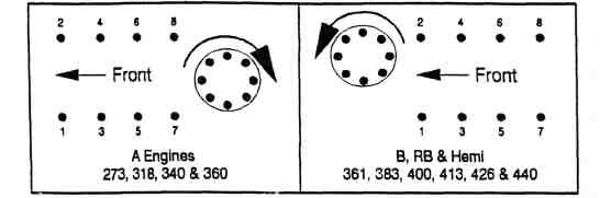
firing order on all Chrysler V8 engines is 1-8-4-3-6-5-7-2. The
"A" engines (273-318-340-360) have clockwise distributor
rotation. The "B" (361-383-400), "RB"
(413-426W-440) engines and the 426 Hemi have counter-clockwise
distributor rotation.
|
|
|
|
|
|
|
|
|
|
|
|
|
|
|
|
|
|
|
|
|
|
|
|
3. Connect a timing light to the
battery and #1 spark plug wire.
4. Check to make sure that the
vacuum advance hose is still disconnected from the distributor.
Temporarily plug the vacuum hose.
5. Start the engine. The ballast
resistor may begin to smoke after the initial startup. This is normal,
but the smoking should stop after the engine has run for a couple
minutes.
6. Set the initial timing at 5° ±
2° BTDC and tighten the distributor hold down bolt so that the
distributor housing will not rotate. Recheck the timing setting to
insure the distributor did not move while being tightened. Reset the
timing if necessary. Disconnect the timing light. See max performance
and suggestions sections!
7. We strongly suggest that you read
the following Max Performance and and Suggestions
sections before testing the vehicle. Leaving the vacuum hose
disconnected and plugged, test the vehicle. After the engine is fully
warmed up, make 2 or 3 full throttle runs. The runs should be made in
high gear if possible. If the engine does not have any detonation
(spark knock), the initial timing setting is OK. If the engine does
detonate, reduce the initial timing by 2°. Rerun the full throttle
test in high gear. Repeat this procedure until the engine does not
detonate.
8. Once the initial timing setting
has been completed, unplug and reconnect the vacuum hose to the
distributor. With the vacuum hose connected, make 2 or 3 steady, part
throttle runs. There should not be any detonation, surges or
hesitation in the engine. If there is, the vacuum advance unit is
adding too much advance to the spark curve. If so, with the engine
turned off, disconnect the vacuum hose. Carefully insert a 3/32 alien
wrench into the fitting where the vacuum hose was connected to the
vacuum advance canister. You will be able to feel the alien wrench go
into an internal alien screw used to adjust the amount of advance
provided by the canister. Be careful not to puncture the diaphragm
inside the canister. With the alien wrench plugged into the adjusting
screw, turn the alien wrench 1/2 turn (180 degrees) clockwise to
reduce the vacuum advance by approximately 2 to 3 degrees. Remove the
alien wrench, reconnect the vacuum hose and rerun the part throttle
test. Repeat this procedure until the detonation, surging and/or
stumbling is eliminated.
IGNITION TUNING FOR MAXIMUM
PERFORMANCE:
Tuning for maximum performance
assumes the rest of the engine is also suitable for maximum
performance. The octane rating of the fuel being used must be
sufficient to accommodate the engine's compression ratio. The engine's
harmonic balancer must have either degree marks or a timing tape
P4529070 which correctly shows up to 60° before top dead
center. The carburetor must be properly jetted so that detonation or
surging is not caused by the fuel mixture being too lean when the
ignition is at maximum advance. The ignition coil and spark plug wires
must be able to deliver sufficient spark to fire the plugs under
maximum engine loading. If you are unsure about any of the above,
consult the Mopar Performance Engine Modifications Manual. The manual
outlines the proper ways to construct a race engine.
If the procedures outlined for
maximum performance are followed and the engine begins to detonate,
you must decrease the timing advances until the detonation is
eliminated. Detonation not only severely reduces power, it also
destroys pistons, rings and rod bearings. DO NOT RUN AN ENGINE THAT IS
DETONATING.
Tools required: Timing light,
3/32 allen wrench, vacuum gauge with long hose, vacuum source
("Mighty Vac") and a friend or helper.
1. Set the basic timing for total
mechanical spark advance.
a. Disconnect and plug the vacuum
advance hose.
b. Connect timing light to the
battery and number 1 spark plug wire.
c. Loosen the distributor hold down
clamp so the distributor housing may be rotated by hand.
d. Start the engine and allow it to
warm up fully.
e. Set the idle speed at 2000 RPM.
See page 7, sections 7 & 8.
f. Set the timing according in
accordance with the following chart:
|
|
|
|
|
|
|
|
|
|
|
|
|
|
|
PAGE 6 of 10
|
|
|
|
|
|
|
|
|
|
|
|
|
|
|
|
|
|
|
|
|
|
|
|
|
|
|
Production - Pre 89 (Iron)
|
|
|
|
|
Production - '89 & Newer
(Iron)
|
|
|
|
|
|
|
|
|
|
|
|
|
|
|
|
|
|
|
|
|
|
|
|
|
|
|
|
|
|
|
|
|
|
|
|
|
|
|
|
B1 (Alum) Under 475 cu. in.
|
|
|
|
|
B1 (Alum) Over 475 cu. in.,
Under 15.0:1 Ratio
|
|
|
|
|
B1 (Alum) Over 475 cu. in.,
Over 15.0:1 Ratio
|
|
|
|
|
|
|
|
|
|
|
|
|
|
|
|
|
|
|
|
|
|
|
|
|
|
g. Tighten the distributor hold
down bolt.
h. Reduce the idle to the original
setting, unplug and reconnect the vacuum advance line.
2. Set the vacuum advance for total
ignition advance.
a. After the basic timing has been
set for total mechanical spark advance, disconnect the vacuum
advance hose at the
carburetor. Connect a vacuum gauge
to the carburetor's vacuum advance port and route the gauge and hose
in to the
passenger compartment. Place the
gauge in a location where an assistant can read the gauge while the
vehicle is
being operated.
b. With the vehicle in operation, note the maximum amount of vacuum
generated by the engine while in gear and being
held at a steady speed between
2000 and 4000 RPM.
C. Stop the vehicle, turn off the
engine and connect a timing light to the battery and number 1 spark
plug wire.
d. Start the engine and raise the idle speed to 2600 RPM. Connect a
vacuum source (Mighty Vac) to the distributor's
vacuum canister and draw vacuum up
to the reading noted in step b.
f. Note the total advance shown on the harmonic balancer.
g. Total Advance, mechanical plus vacuum, should be set according to
the following chart:
|
|
|
|
|
|
|
|
|
|
|
|
|
|
|
h. Refer to section #8, page 7
before making any tests/changes in the advance setup. Disconnect the
vacuum source and insert a 3/32 alien wrench into the internal
vacuum canister adjusting screw. Turn the alien screw (clockwise to
decrease, counterclockwise to increase) to obtain the correct
setting. Reconnect the vacuum source and recheck the timing.
Continue repeating this procedure until the correct setting is
obtained.
i. Remove the timing light and
vacuum source. Reconnect the vacuum advance hose. Reset the idle
speed to your original setting.
Trouble Shooting:
If the vehicle does not operate
properly, refer to the following trouble shooting chart for possible
causes of the malfunction. If you are unable to correct the problem,
call the Mopar Performance Tech Hotline at (248) 969-1690, Monday
through Friday, 9:00 -12:00 and 1:00 - 5:00, EST.
1. Engine turns over but will not
start:
a. Recheck all connections for
being loose or poorly connected.
b. Check to see if battery voltage
(12 volts) is being supplied to the ballast resistor when the
ignition key is held
in the start position. If not,
clean or repair all the electrical connections from the battery to
the ballast
resistor,
c. Check to ensure that the ECU is grounded. This usually occurs
when the ECU is bolted down, but a separate ground
wire from the ECU bolt to the body
or engine or battery may be required. See page 7, section #6.
d. Recheck the Main Ignition Feed splice if one was required.
e. Double check the distributor position to be sure that the
distributor is NOT installed 180 degrees out of phase -
rotor points the wrong way. Check
this against the valve position on the #1 cylinder.
2. Engine idles rough and stalls:
a. Check the battery's state of
charge. It must be a minimum of 12.5 volts with the engine running.
(Minimum specific
gravity must be no less than
1.250.)
b. The coil output may be low. Have the ignition coil checked for
maximum output. It should be at least 20 KV. 40
KV or higher is preferred on a
race/performance vehicle,
c. Check for carbon tracks in the distributor.
d. Check spark plug wires especially if they have not been replaced.
3. High speed miss:
a. Check for loose connections or
poor grounds.
b. Check for dirty or worn spark plugs.
c. Check for faulty spark plug
wires or poor connections on new wire sets.
d. Check the battery voltage at
the ballast resistor. It must be no lower than 12.5 volts. This is
especially important on cars with alternator cut outs or cars with
no alternator. If the vehicle uses an alternator cut out, test the
voltage with the alternator turned off.
|
|
|
|
|
|
|
|
|
|
|
|
|
|
|
PAGE 7 of 10
|
|
|
|
|
|
|
|
|
|
Helpful Suggestions:
1. If you are using an electric
tachometer, the wire normally connected to the distributor should be
connected to the Negative side of the coil. If this fails to operate
your tach correctly, contact the tachometer manufacturer for the
correct wiring instructions.
2. If you are using an engine speed
limiter, commonly called an RPM or rev limiter, splice the normally
open side of the limiter into the grey wire leading to the
distributor. Hake sure it is a clean splice, securely connected and
taped to prevent moisture or accidental grounding. Connect the
limiters "common" terminal to ground.
3. Battery voltage is very critical
to electronic ignition systems. You may want to use a Mopar
Performance High Output Voltage Regulator (P3690731 for 1970 &
newer, P3690732 for 1969 and older). They are especially useful if you
use an alternator cutout during racing. The MP voltage regulators are
set for a constant alternator output of 14.5 volts, they should not be
used for continuous operation. Note: for the '69 and older cars, the
electronic regulator P3690732 should be considered a race only option
unless your engine has a high rpm miss.
4. For any Chrysler performance or
racing questions you may have, call the Mopar Performance Tech Hotline
at (248) 853-7290. The service is available Monday through Friday,
9:00 - 12:00 and 1:00 - 5:00 Eastern Standard Time. Help is just a
phone call away.
5. In your engine compartment,
locate the master disconnect connector (see page 9) also called
the bulkhead connector which is located on the firewall, usually near
the steering column. If the car is an older model, it is a good idea
to unplug this connector, clean it and re-install it.
6. There are three main grounds
in the typical production car: one from the battery to the body/frame,
one from the frame/body to the engine and one from the frame to the
body. Since uni-body cars have the frame welded to the body, this last
one is not always used. However, many models isolate the front frame
rails from the rest of the uni-body for better ride or improved sound
isolation. Then this frame to body ground becomes important. If the
battery is moved to the trunk, then it can only be grounded to the
body or frame in this area. That makes these three grounds more
important. We recommend that the grounds be located and checked -
replace/upgrade as required.
7. Detonation is a function of the
fuel that is being used, which varies with the area in the country,
the engine's actual compression ratio and the spark advance. Race gas
costs from $3 to $7 per gallon so that is not a good solution for
non-racing applications. The best pump premium is usually required for
performance applications. Once the engine is built and installed in
the vehicle, the compression ratio is basically fixed. That means that
the spark advance is the only aspect left that can be adjusted, if the
engine has detonation.
8. Total mechanical spark advance is
the sum of the distributor advance, and the initial advance. The
distributor advance is the centrifugal advance which varies with RPM.
For max performance, this distributor becomes fully advanced at 2000
rpm. At that point, the total mechanical advance - sum of initial
advance and centrifugal advance - should equal the number shown on
page 5 or 6 for your specific engine. This is the max performance
setting. Then the vacuum advance is added on top of this but it goes
away at WOT (Wide Open Throttle) because the vacuum goes to zero at
WOT. Page 6 lists the Total Advance - sum of total mechanical advance
and the vacuum advance - which shows about 13 degrees for the vacuum
advance. On pump gas, with the full total advance. the engine
may detonate with this much advance. The best performance solution to
this problem is to decrease the amount of vacuum advance that is used.
|
|
|
|
|
|
|
|
|
|
|
PAGE 8 of 10
|
|
|
|
|
|
|
|
|
|
|
|
|
|
|
|
|
|
|
|
|
|
|
|
MASTER DISCONNECT CHART
CAVITY LOCATION -
MAIN IGNITION FEED
|
|
|
|
|
|
|
|
|
|
|
|
|
|
|
|
|
|
|
|
|
|
|
|
|
|
|
|
|
|
|
|
|
|
|
|
|
|
|
|
|
|
|
|
|
|
|
|
|
|
|
|
|
|
|
|
|
|
|
|
|
|
|
|
|
|
|
|
|
|
|
|
|
|
|
|
|
|
|
|
|
|
|
|
|
|
|
|
|
|
|
|
|
|
|
|
|
|
|
|
|
|
|
|
|
|
|
|
|
|
|
|
|
|
|
|
|
|
|
|
|
|
|
|
|
|
|
|
|
|
|
|
|
|
|
|
|
|
|
|
|
|
|
|
|
|
|
|
|
|
|
|
|
|
|
|
|
|
|
|
|
|
|
|
|
|
|
|
|
|
|
|
|
|
|
|
|
|
|
|
|
|
|
|
|
|
|
|
|
|
|
|
|
|
|
|
|
|
|
|
|
|
|
|
|
|
|
|
|
|
|
|
|
|
|
|
|
|
|
|
|
|
|
|
|
|
|
|
|
|
|
|
|
|
|
|
|
|
|
|
|
|
|
|
|
|
|
|
|
|
|
|
|
|
|
|
|
|
|
|
|
|
|
|
|
|
|
|
|
|
|
|
|
|
|
|
|
|
|
|
|
|
|
|
|
|
|
|
|
|
|
|
|
|
|
|
|
|
|
|
|
|
|
|
|
|
|
|
|
|
|
|
|
|
|
PAGE 9 of 10
|
|
|
|
|
|
|
|
|
|
|
|
|
|
|
MASTER DISCONNECT CHART
CONNECTOR STYLES
|
|
|
|
|
|
|
|
|
|
|
|
|
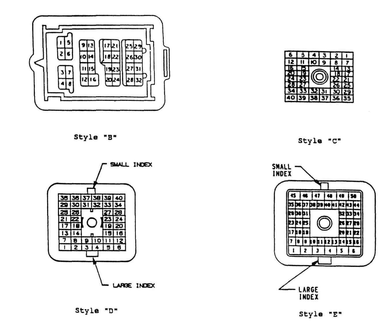
Using the chart on page 7, determine
which
Master Disconnect Connector was used on the
vehicle and in which cavity the Main Ignition
Feed is located. The Main Ignition Feed
wire should be a dark blue wire for all
Cars, and the '86 to 91 Pick Ups and Vans
The '80 to '85 Pick Ups and Vans should have
a red Main Ignition Feed wire.
|
|
|
|
|
|
|
|
|
|
|
|
|
|
|
|
|
|
|
|
|
|
|
|
|
|
|
PAGE 10 of 10
|
|
|
|
|
|
|
|
|
|
|
|
Wiring for a Street Rod:
This diagram is included for the
Street Rod builder. Because Street Rods are constructed from any make
of pre-1948 body and may use the original wiring harness, an
aftermarket wiring harness or a homemade wiring harness, it is
impossible to give proper wiring connections for each application.
Please refer to the figure below to correctly wire the Mopar
Performance ignition kit. The wire marked "R" is the Main
Ignition Feed wire and must have 12 volts supplied whenever the
ignition key is an the Run or the Start positions. The wire
marked "S" is the Resistor Bypass wire and must have 12
volts supplied whenever the ignition key is in the Start position.
Although complete and quite functional, this diagram represents the
very basic wiring system - only what is required to start and run the
vehicle. Please consult an electrical wiring diagram for the vehicle
you are working with to identify the proper wires for making these
connections. If you are making your own wiring harness, you may wish
to refer to page 10 and "Creating Wiring Harnesses for a New
Vehicle", for a more complete wiring diagram. For installation of
this kit, follow the "Replacing Point Type Ignition"
instructions on page 1, remembering that the wires being spliced into
at the ballast resistor may need to be fabricated.
|
|
|
|
|
|
|
|
|
|
|
|
|
|
|
|
|
|
|
|
This page was last
updated Dec 8, 2002. Send us your feedback